Data transmission device and a method for activating a data transmission

Active Publication Date: 2012-12-20
FRAUNHOFER GESELLSCHAFT ZUR FOERDERUNG DER ANGEWANDTEN FORSCHUNG EV
View PDF8 Cites 38 Cited by
  • Summary
  • Abstract
  • Description
  • Claims
  • Application Information

AI Technical Summary

Benefits of technology

[0016]The present invention is based on the finding that an energy-intensive data transmission means may be set into an idle state from which it may be activated by means of a wake-up receiver into an operating state. The wake-up receiver is implemented, in response to an initiation signal (or wake-up signal), to activate the data transmission means from the idle state into the operating state. Here, the initiation signal is implemented such that it comprises additional information (data transmission information), for example to activate the data transmission means at a certain point in time, i.e. not until a data transmission may in fact take place. Alternatively, the data transmission means is initiated with specific network parameters or data transmission parameters contained in the initiation signal. Thus, embodiments of the present invention use the wake-up signal of the wake-up receiver to transmit additional information for the purpose of enabling the data transmission means to operate as efficiently as possible: e.g., it is not switched on until the point in time when either a synchronization takes place or a data transmission may start, wherein simultaneously network parameters may be passed on so that a time loss with respect to the network setup is minimized
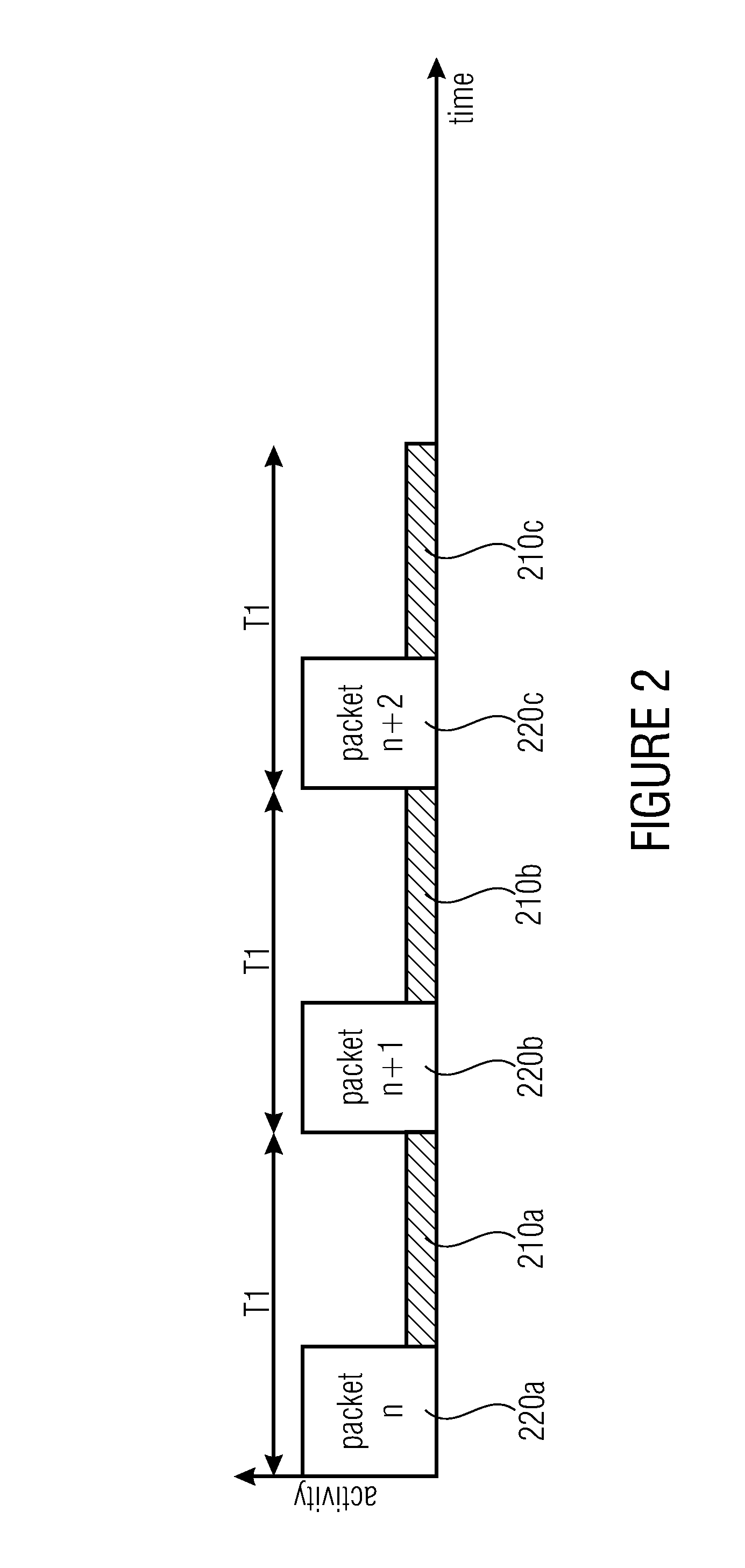
[0017]Wake-up signaling thus serves, for example, to activate a synchronous, wireless network operating with the TDMA method and a low duty cycle, on demand and with selectable transmission parameters. Due to the minimum latency, events may thus be transmitted quickly. The wake-up signaling further reduces, with previously non-synchronous networks, the energy consumption during the synchronization phase, because a waking up of the nodes does not have to be ready to receive from the wake-up time to the next synchronization message, but is informed, for example, when the synchronization message is sent, wherein the synchronization message may, for example, include the above-described beacon. Finally, by means of the wake-up signaling, transmission parameters may be reselected (i.e. changed), which may be adapted to the time performance of the protocol, e.g. to the data throughput to be expected.
[0018]Embodiments thus aim at the reduction of the energy consumption in the operation, for example, of wireless synchronous sensor networks and the reduction of latencies in data transmission. Sensor networks are thus especially interesting as, in particular for these networks, very long idle phases exist, from which networks are to set up very quickly in order to transmit a sensor event to a receiver without time loss. The sensor signal may, for example, include exceeding a sensor temperature or a response of a motion detector or an opening of a door or similar events.
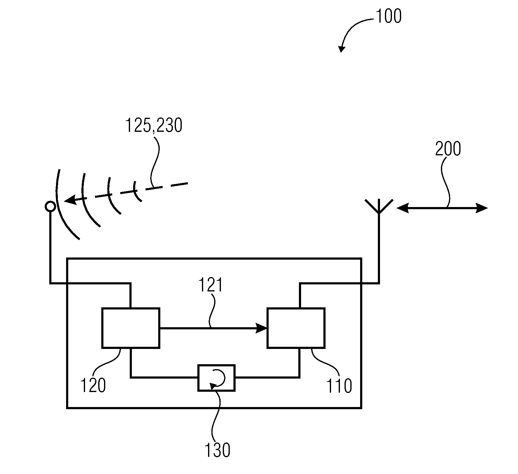
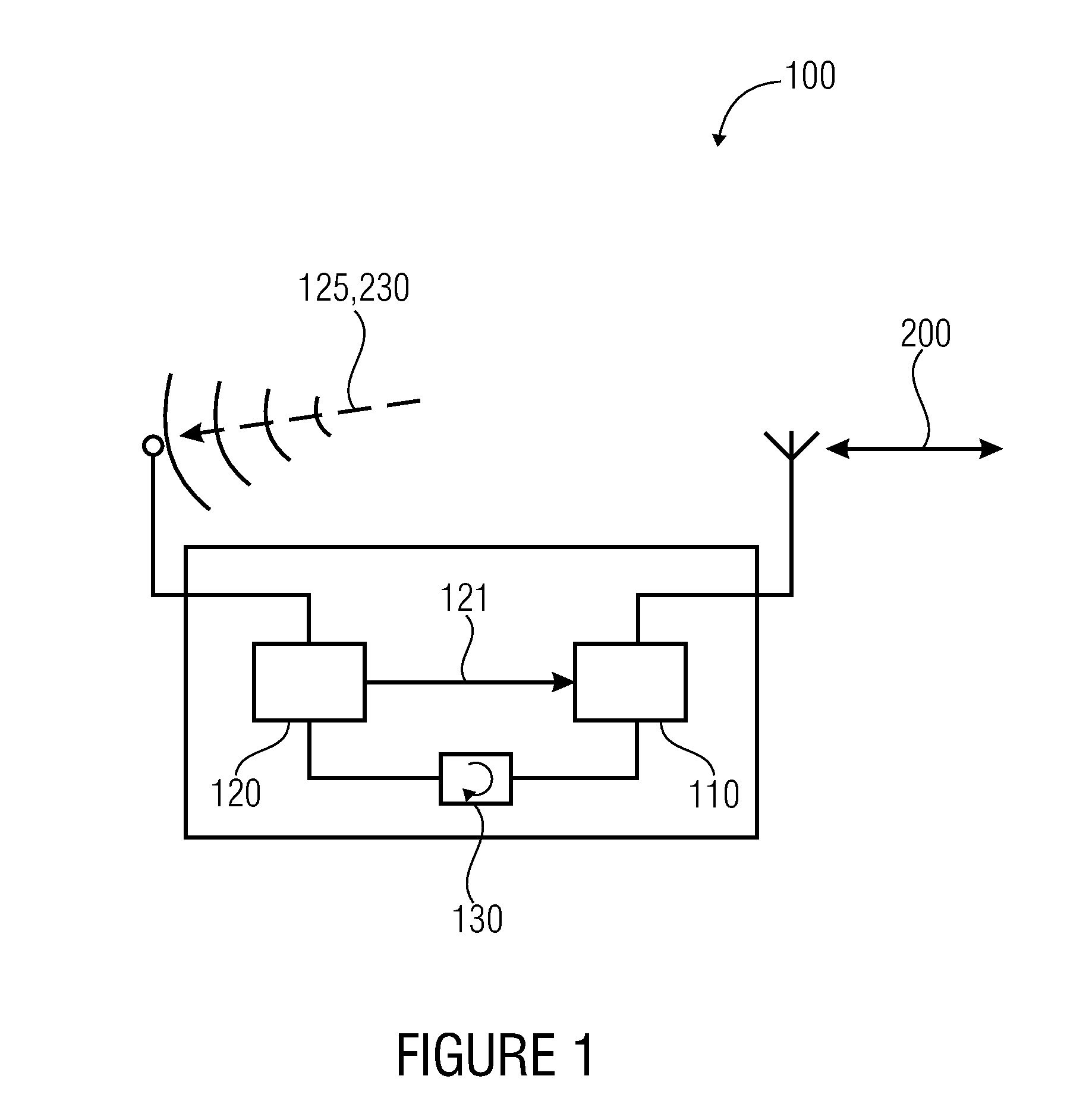
[0019]According to further embodiments, each radio node (or generally network nodes) in this respect, apart from a regular transmit and receive circuit (data transmission means or main receiver) comprises a very simple wake-up receiver (WUR) which is known for an extremely low energy consumption (e.g. a current consumption of less than 100 μA or less than 10 μA or less than 1 μA) and may thus continuously remain in the receive mode.
[0021]Embodiments also describe a method for a premature activation of a duty cycle-based network which may be synchronous or non-synchronous (e.g. a wireless network) in the sleep phase without synchronization losses. These methods are advantageous as the transmission parameters may be reset and adapted to the data volume. If the individual radio nodes have not been synchronous before, the inventive method allows a reduction of the energy consumption during the synchronization phase.
[0022]By the special setup of the wake-up signaling with additional information, thus the energy consumption during synchronization may be clearly minimized The activation of a previously already synchronous wireless network is possible without a synchronization loss and with possibly changed transmission parameters (like, for example, changed frame length, time slot length, frame setup). The wake-up signal in this case contains, for example, information with respect to transmission parameters, which may, for example, include the frame setup and the time of the next data transmission.

Problems solved by technology

Thus, in particular the receiver is not active most of the time and thus not reachable for a radio communication (latency).
In this scenario, thus an increase in the reaction time or an unwantedly long latency results.
The duty cycle thus has to be very short.
The achievable power consumption is only in an order of magnitude of 100 microamperes, however.
Thus, they are suitable for steady-state operation, but may generally not be used as a main receiver as their sensitivity is too low.
With very long sleep times between the phases in which a data transmission may take place, drift effects may have a negative effect.
One possibility is additional synchronization messages which only serve for synchronization but do not enable a data transmission.
With very current-saving applications, sleep times are very long and thus also latency.
Thus, a long time passes until an event may be reported across the network.
From the above-mentioned, for the described access methods a series of problems result for the network.
Thus, for example, current-saving synchronous wireless sensor networks generally operate with the TDMA method so that they are not ready to receive continuously, but only at discrete points in time.
This is not acceptable for many applications.
A further problem results from the limited operation time with battery operation.
This, again, involves the disadvantage of a very long latency.
A further problem results from the fact that with very long sleep times which may, for example, be in a range of several hours, drift effects may have a negative effect.
In any case, thus the energy consumption would rise again.
This compromise limits the energy-saving potential considerably.
Finally, it is disadvantageous in standard technology that for receiving synchronization signals generally the main receiver is used, which again leads to an increased current or energy consumption.

Method used


Image

  • Data transmission device and a method for activating a data transmission
  • Data transmission device and a method for activating a data transmission
  • Data transmission device and a method for activating a data transmission

Examples


Embodiment Construction

[0032]With respect to the following description, it should be noted that, in the different embodiments, same or functionally same functional elements comprise the same reference numerals and thus the description of these functional elements in the different embodiments is mutually interchangeable. Likewise, the selected order may be regarded as an example, so that exchanges of the individual elements are also possible.

[0033]FIG. 1 shows an embodiment for a data transmission device 100 comprising a data transmission means 110 and a wake-up receiver 120. The data transmission means 110 may be activated to change from an idle state into an operating state and in the operating state to execute a data transmission 200 with a communication partner. The wake-up receiver 120 is implemented to be ready to receive an initiation signal 125 during the idle state of the data transmission means 110 and to activate the data transmission means 110 in response to the initiation signal 125. This may,...


PUM


Abstract

A data transmission device has a data transmitter and a wake-up receiver. The data transmitter is activable to change from an idle state into an operating state and to execute a data transmission with a communication partner in the operating state. The wake-up receiver is implemented to be ready to receive an initiation signal during the idle state of the data transmitter and to activate the data transmitter in response to the initiation signal. The wake-up receiver is further implemented to extract data transmission information from the initiation signal to determine a time for activating the data transmitter depending on the data transmission information or to activate the data transmitter such that the data transmitter executes the data transmission depending on the data transmission information.

Description

CROSS-REFERENCE TO RELATED APPLICATIONS[0001]This application is a continuation of copending International Application No. PCT / EP2010 / 068323, filed Nov. 26, 2010, which is incorporated herein by reference in its entirety, and additionally claims priority from German Application No. DE 10 2009047199.5, filed Nov. 26, 2009, which is also incorporated herein by reference in its entirety.BACKGROUND OF THE INVENTION[0002]The present invention relates to a data transmission device, a data transmission system and a method for activating a data transmission and, in particular, to a device and a method of a wake-up signaling and a simultaneous network setup.[0003]In order for several participants (e.g. radio nodes) to be able to transmit data via a network, it is, for example, standard practice to use a time-controlled media access method. Network protocols for wireless networks in this respect frequently use TDMA methods (TDMA=time division multiple access). The radio nodes of such networks...

Claims


Application Information

Patent Timeline
IPC IPC(8): H04W52/02H04W56/00
CPCY02B60/50H04W52/0235Y02D30/70
Inventor STURM, ROLANDMILOSIU, HEINRICHGRILLBORZER, ARTURGEHRMANN, VOLKERTITTEL, MARTINHUPP, JUERGENFLUEGEL, CHRISTIAN
Owner FRAUNHOFER GESELLSCHAFT ZUR FOERDERUNG DER ANGEWANDTEN FORSCHUNG EV
Why Eureka
Try Eureka