Drawing apparatus, and method of manufacturing article

a technology of drawing apparatus and manufacturing method, applied in the direction of photomechanical apparatus, instruments, therapy, etc., can solve the problems of uneven heat amount (heat density), uneven deformation, and heat can be problematic, and achieve the effect of reducing the uneven deformation of the aperture array member

Inactive Publication Date: 2014-11-27
CANON KK
View PDF4 Cites 2 Cited by
  • Summary
  • Abstract
  • Description
  • Claims
  • Application Information

AI Technical Summary

Benefits of technology

[0007]The present invention provides, for example, a drawing apparatus advantageous in terms of reducing uneven deformation of an aperture array member caused by a charged particle beam incident thereon.

Problems solved by technology

The heat can be problematic when the irradiation current is increased to obtain high throughput.
However, unevenness of irradiation of charged particle beams or a decrease in numerical aperture caused by hydrocarbon adhesion in the apertures of an aperture array member results in an uneven heat amount (heat density) in the aperture array member that determines the final shape of a charged particle beam.
Such an uneven heat amount causes uneven deformation (including uneven changes of aperture positions) of the aperture array member by uneven thermal expansion.

Method used


Image

  • Drawing apparatus, and method of manufacturing article
  • Drawing apparatus, and method of manufacturing article
  • Drawing apparatus, and method of manufacturing article

Examples


first embodiment

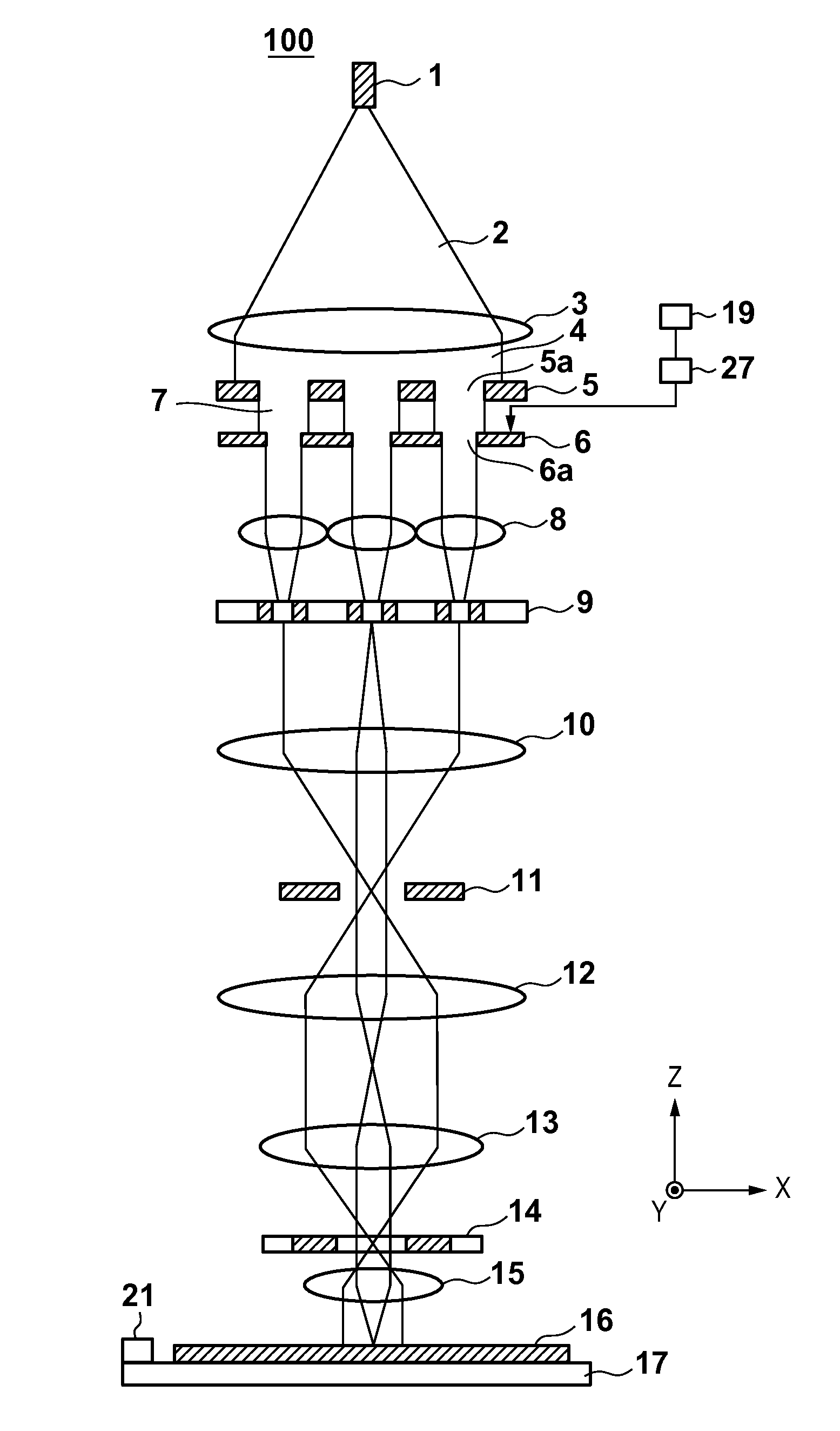
[0015]FIG. 1 is a schematic view showing the arrangement of a drawing apparatus 100 according to the first embodiment of the present invention. The drawing apparatus 100 is a lithography apparatus that performs drawing on a substrate with a plurality of charged particle beams (that is, draws a pattern on a substrate). The charged particle beam is not limited to an electron beam and can be, for example, an ion beam or the like.

[0016]The drawing apparatus 100 includes a charged particle source 1, a collimator lens 3, a first aperture array 5, a second aperture array 6, a focusing lens array 8, a blanker array 9, and a charged particle lens 10. The drawing apparatus 100 also includes a stop aperture array 11, charged particle lenses 12 and 13, a deflector 14, a charged particle lens 15, a substrate stage 17, a control unit 19, and a measurement unit 21.

[0017]The charged particle source 1 is a thermionic charged particle source including, for example, LaB6 or BaO / W (dispenser cathode) i...

second embodiment

[0031]FIG. 3 is a schematic view showing the arrangement of a drawing apparatus 100A according to the second embodiment of the present invention. The drawing apparatus 100A is a lithography apparatus that performs drawing on a substrate with a plurality of charged particle beams (that is, draws a pattern on a substrate). The drawing apparatus 100A includes a first shield electrode 30 and a second shield electrode 31 in addition to the components of the drawing apparatus 100 shown in FIG. 1.

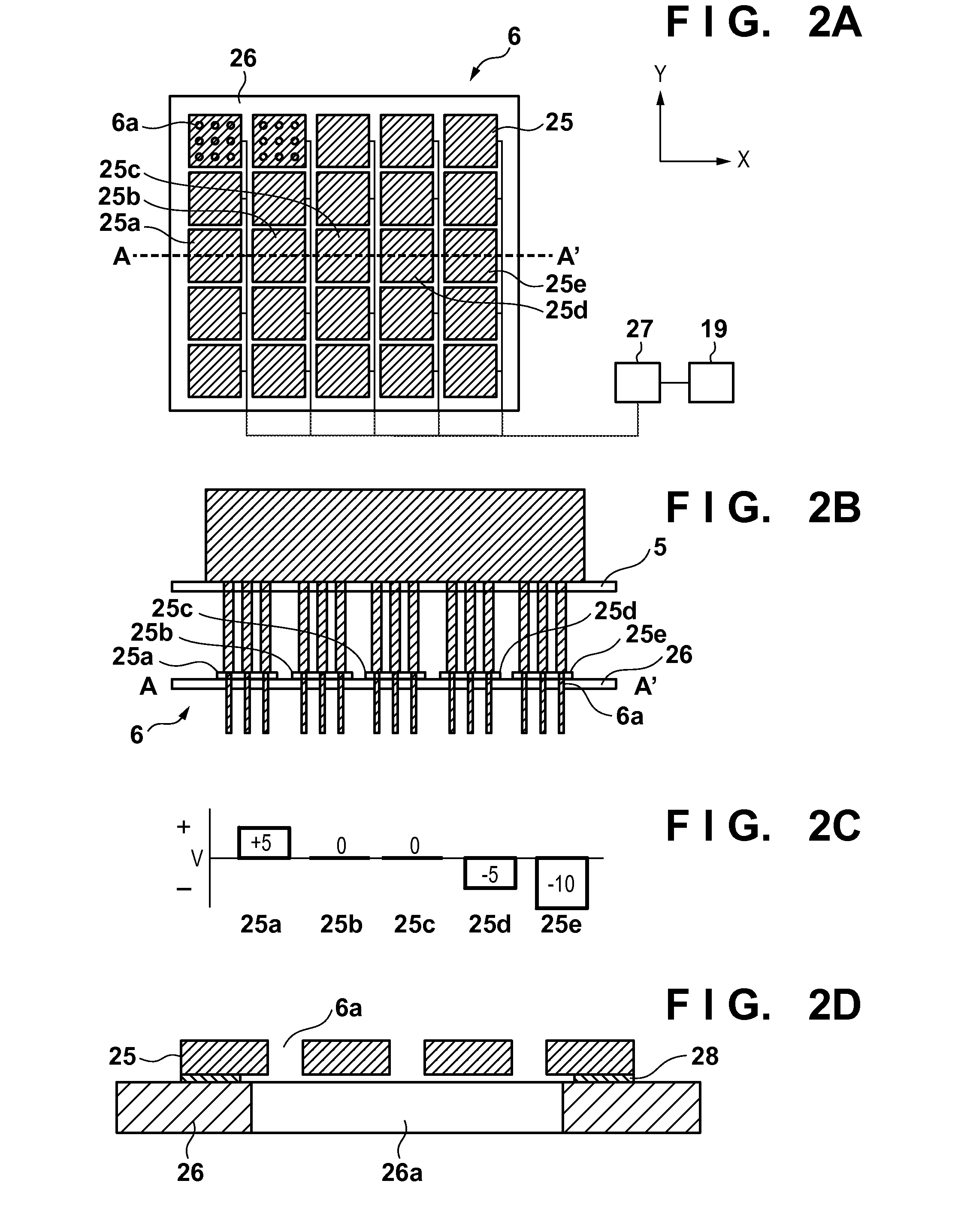
[0032]The first shield electrode 30 and the second shield electrode 31 will be described with reference to FIGS. 4A to 4C.

[0033]As shown in FIG. 4A, the first shield electrode 30 is arranged on the side of a charged particle source 1 with respect to a second aperture array 6 (a side opposite to a substrate), more specifically, between a first aperture array 5 and the second aperture array 6. The first shield electrode 30 has a plurality of apertures (second apertures) 30a corresponding to a plural...


PUM


Abstract

The present invention provides a drawing apparatus for performing drawing on a substrate with a plurality of charged particle beams, the apparatus including an aperture array member in which a plurality of first apertures, for generating the plurality of charged particle beams, is formed, and a generating device configured to individually generate electric potentials in a plurality of regions of the aperture array member, wherein each of the plurality of regions corresponds to at least one of the plurality of first apertures.

Description

BACKGROUND OF THE INVENTION[0001]1. Field of the Invention[0002]The present invention relates to a drawing apparatus, and a method of manufacturing an article.[0003]2. Description of the Related Art[0004]As a drawing apparatus for performing drawing on a substrate with charged particle beams, Japanese Patent Laid-Open No. 9-7538 proposes a drawing apparatus including a charged particle optical system for each charged particle beam. In such a drawing apparatus, since the charged particle optical systems individually exist, a crossover where all the plurality of charged particle beams focus is not formed. Hence, the drawing apparatus is advantageous in increasing the number of charged particle beams and thus increasing the irradiation current upon drawing (that is, improving the throughput) because the influence of the space-charge effect (Coulomb effect) is small.[0005]On the other hand, increasing the irradiation current to obtain high throughput also causes an increase in the amoun...

Claims


Application Information

Patent Timeline
Patent Type & Authority Applications(United States)
IPC IPC(8): H01J37/317H01J37/30
CPCH01J37/3002H01J37/3174H01J37/09H01J37/3177H01J2237/0453H01J2237/047
Inventor NAKAMURA, KEISUKE
Owner CANON KK
Why Eureka
Try Eureka