Plate heat exchanger and method of using

a heat exchanger and plate technology, applied in heat exchange apparatus, refining by heating/cooling, lighting and heating apparatus, etc., can solve the problems of high temperature, high temperature, and high temperature of heat exchangers, and achieve the effect of lowering the enthalpy and high enthalpy

Inactive Publication Date: 2014-11-20
UOP LLC
View PDF9 Cites 0 Cited by
  • Summary
  • Abstract
  • Description
  • Claims
  • Application Information

AI Technical Summary

Benefits of technology

[0021]One aspect of the invention is a process for heating a cold stream, such as a feed to a reaction zone, with a hot stream, such as a reactor effluent. In one embodiment, the process includes providing a plate heat exchanger. The plate heat exchanger comprises a plurality of corrugated plates forming cold flow channels and hot flow channels, a cold inlet in fluid communication with the cold flow channels, a cold outlet in fluid communication with the cold flow channels, a hot inlet in fluid communication with the hot flow channels, a hot outlet in fluid communication with the hot flow channels. The cold stream is introduced to the cold inlet and the hot stream is introduced to the hot inlet and heat is exchanged from the hot stream to the cold stream. The cold stream has a higher enthalpy at the outlet than at the inlet, and the hot stream has a lower enthalpy at the outlet than at the inlet. At least one of the cold inlet, the cold outlet, the hot inlet, the hot outlet, and the plurality of plates is made of: a first stainless steel alloy comprising 0.005 to 0.020 wt % carbon, 9.0 to 13.0 wt % nickel, 17.0 to 19.0 wt % chromium, 0.20 to 0.50 wt % niobium, and 0.06 to 0.10 wt % nitrogen; or a second stainless steel alloy comprising 0.0005 to 0.020 wt % carbon, 10 to 30 wt % nickel, 15-24 wt % chromium, 0.20 to 0.50 wt % niobium, 0.06 to 0.10 wt % nitrogen, up to 5 wt % copper, up to 1.00 wt % silicon, up to 2.00 wt % manganese, and 0.3 to 7 wt % molybdenum.

Problems solved by technology

Many types of hydrocarbon processing operations are carried out under relatively harsh operating conditions, including high temperatures and / or pressures and within various harsh chemical environments.
This and other specialty austenitic stainless steels have been used in these applications but are susceptible to high temperature H2S, sulfur, and chloride-SCC corrosion and high temperature hydrogen attack issues that are present in these processes.
Many metals, including austenitic stainless steels, can be subject to a highly localized form of corrosion known as stress-corrosion cracking (SCC).
SCC often takes the form of branching cracks in apparently ductile material and can occur with little or no advance warning.
In low pressure vessels, the first sign of stress corrosion cracking is usually a leak, but there have been instances of catastrophic failures of high pressure vessels due to stress corrosion cracking.
Stress corrosion cracking occurs when the surface of the material exposed to a corroding medium is under tensile stress (applied or residual) and the corroding medium specifically causes stress corrosion cracking of the metal.
One particularly harsh environment in which austenitic stainless steels are typically observed to undergo stress corrosion cracking is an environment containing halides, usually in the form of inorganic chlorides.
The presence of chlorides along with an aqueous phase and tensile stresses can result in chloride stress corrosion cracking (“chloride-SCC”) of austenitic stainless steels.
In addition, while high temperatures may reduce the amount of time required for a particular chloride concentration to result in chloride-SCC, lower temperatures can cause chlorides to condense on surfaces, thereby increasing the concentration of the chlorides on the surfaces.
Thus, chloride-SCC can be problematic at many temperature ranges.
One particularly problematic area of chloride-SCC is in condensers where chloride condenses and concentrates on surfaces of the vessel.
The precipitation of chromium depletes the chromium content adjacent to the grain boundaries, forming chromium depleted zones and drastically reducing the corrosion and / or cracking resistance in corrosive environments in these zones.
The PTA can attack the chromium depleted zones formed by sensitization, causing corrosion and ultimately polythionic acid stress corrosion cracking (PTA-SCC) where the vessel is put under tensile stresses either by being pressurized or by having residual stresses from, for example, welding during fabrication.
Each of these processes is time consuming and impractical during the operation of an oil refinery complex because it requires additional materials and additional downtime of the particular equipment to perform the purge or neutralization steps.
Moreover, the catalyst in the reactor can be poisoned if trace levels of the chemicals remain, which is often the case.
However, such austenitic stainless steels are also susceptible to PTA-SCC as a result of exposure to polythionic acid, since the operating conditions of many hydrocarbon treatment processes fall within the time at temperature at which sensitization occurs.
Similarly, these materials are still susceptible to chloride-SCC through exposure to chlorides, oxygen, water, and stress at sufficient times and temperatures.
The need for special procedures during shutdown and startup of a refinery complex affects not only costs, but also production time since they take a certain amount of time to carry out.
However, even with these precautions, chloride corrosion of welded plate heat exchangers is often observed when liquid water is present in the feed leading to chloride pitting, chloride pitting due to under-deposit corrosion, and when a water dew-point occurs during regeneration of a fixed bed reforming unit leading to chloride pitting, and chloride-SCC due to the presence of chlorides, oxygen, and water.
Any failure due to corrosion or cracking will reduce product quality by contaminating the product stream with the feed stream.
In addition, some welded plate heat exchangers are damaged by thermal stress which can cause mechanical damage to the heat exchanger.
This type of mechanical damage accounts for the majority of all damage that causes bundle cross leakage.
Flow mal-distributions can occur when there is a fouling of the bundle, when there is a sudden plugging of the bundle, when there is plugging of a distributor, or when there are low velocities resulting in poor liquid flow up in the bundle.
Thermal stress damage that causes bundle cross leaking is costly to the end user because it results in cross-leakage of the higher pressure stream into the lower pressure stream resulting in a reduction in heat transfer efficiency, as well as potentially contaminating a product stream with a feed stream.
This damage can result in reduced throughput, reduced product quality, and eventually may require shutdown to repair or replace the heat exchanger.
In corrosion and SCC cases, the bundles cannot be repaired because the damage typically occurs to most of or all the plate channels, requiring replacement of the bundle or the entire heat exchanger.
However, when 10-20% or more of the channels are plugged, the resulting increase in pressure-drop can significantly reduce throughput.
Furthermore, repaired bundles can be more susceptible to further damage by thermal stresses.

Method used


Image

  • Plate heat exchanger and method of using
  • Plate heat exchanger and method of using
  • Plate heat exchanger and method of using

Examples


Embodiment Construction

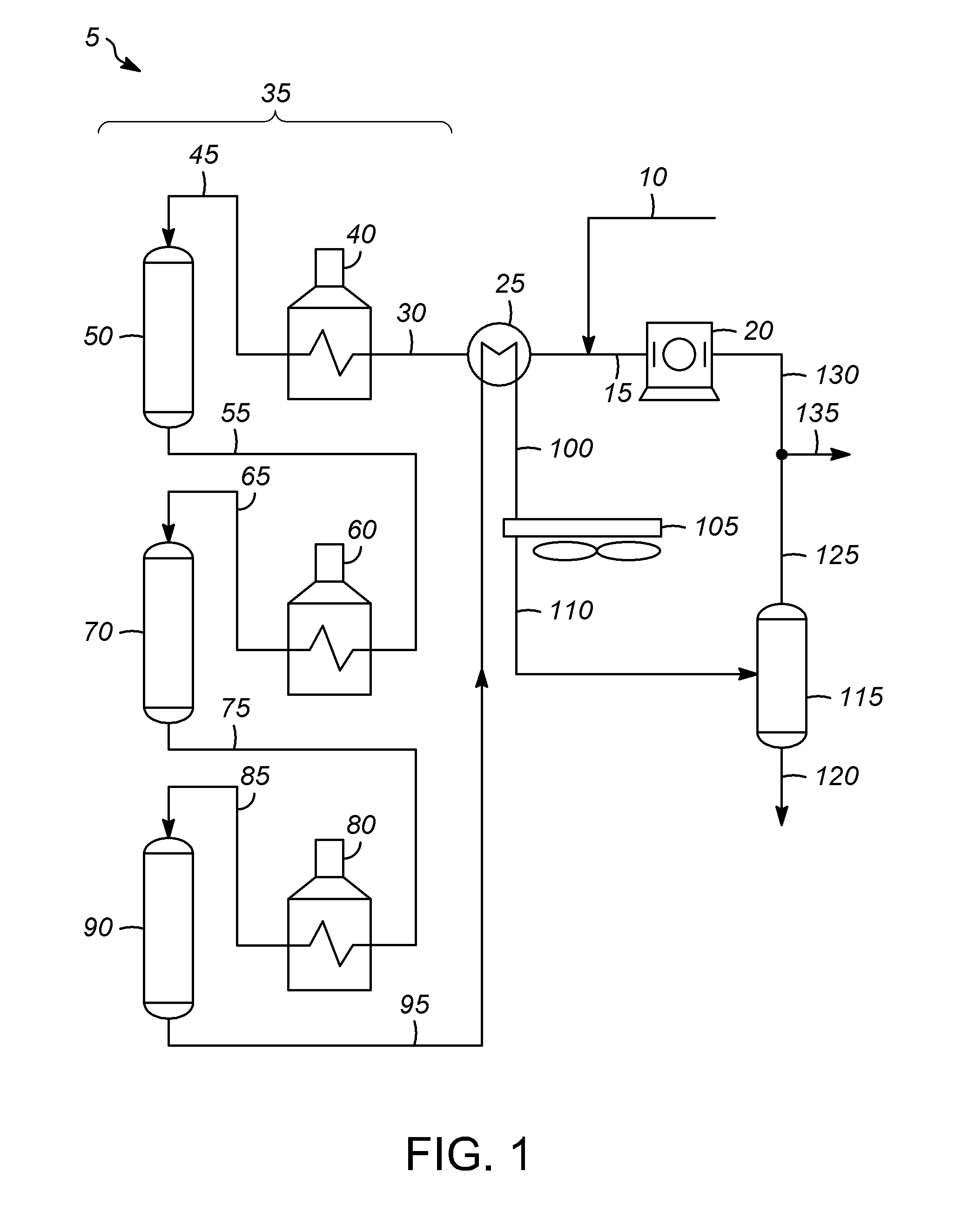
[0028]Processes for treating a hydrocarbon cold stream including one or more different hydrocarbons and which may include other components and / or impurities typically include flowing the hydrocarbon stream through various pieces of equipment. The equipment may be included as part of a larger oil refinery complex capable of performing one or more particular types of hydrocarbon conversion or treatment processes for converting or treating one or more components of the hydrocarbon cold stream to form a desired product. Heat is applied to the hydrocarbon stream and / or the equipment during operation. Heat may be applied to the hydrocarbon stream while it is within or before entering the equipment to raise the temperature thereof to a processing temperature. Particular process parameters or operating conditions, such as temperature, pressure, and space velocity, are typically process specific and are selected to promote the particular reactions or treatment steps of the particular process...


PUM

PropertyMeasurementUnit
temperatureaaaaaaaaaa
temperaturesaaaaaaaaaa

Abstract

A process for heating a cold stream with a hot stream is described. At least one of the cold inlet or outlet, the hot inlet or outlet, the cold inlet or outlet header, the hot inlet or outlet header, and the plurality of plates is made of one of two stainless steel alloys. One alloy has higher molybdenum content with copper for improved corrosion resistance and is resistant to chloride pitting, chloride SCC, and PTA SCC. The other alloy has significantly higher tensile and yield strength, which will reduce the susceptibility of the plate bundle to thermal stress damage.

Description

BACKGROUND OF THE INVENTION[0001]Oil refineries typically incorporate one or more different processes for treating and / or converting hydrocarbons, such as, for example, those present in crude oil or another naturally occurring source, to produce specific hydrocarbon products with properties that are useful for particular applications.[0002]To carry out the refining or processing operations to treat crude oil and other hydrocarbons to form usable products, oil refineries typically include one or more complexes or groups of equipment designed for carrying out one or more particular treating or conversion processes to prepare desired final products. In this regard, the complexes each may have a variety of interconnected equipment or vessels including, among others, tanks, furnaces, distillation towers, reactors, heat exchangers, pumps, pipes, fittings, and valves.[0003]Many types of hydrocarbon processing operations are carried out under relatively harsh operating conditions, including...

Claims


Application Information

Patent Timeline
Patent Type & Authority Applications(United States)
IPC IPC(8): C10G31/06
CPCC10G31/06C10G59/02
Inventor DALY, PHILLIP F.BRADLEY, STEVEN A.
Owner UOP LLC
Why Eureka
Try Eureka