
Self-osteotomizing bone implant and related method

Active Publication Date: 2014-11-06
ZADEH PARSA T
View PDF28 Cites 25 Cited by
  • Summary
  • Abstract
  • Description
  • Claims
  • Application Information

AI Technical Summary

Benefits of technology

The patent text describes an implant that can be used to securely attach dental prostheses to bone. The implant has a head that is designed to hold a dental abutment, which helps to keep the implant in place. To install the implant, a pilot hole is drilled in the bone and the implant is securely inserted. The implant is then rotated to create an osteotomy, or a cut in the bone, which helps to speed up the healing process and reduce the amount of autogenous bone material required for grafting. Overall, this design of the implant makes it easier and more efficient to securely attach dental prostheses to bone.

Problems solved by technology

This diverse structure of the bones from one part of the body to another and within the same area from cortex (outer layer) to medulla (inner layer), makes the bone an unpredictable material for implants and fasteners.
Inconsistencies in vital bone structure have resulted in many limitations in the current procedures.
Therefore, while the drilling of the bone does not contribute to post-operative pain, placement of current bone screws or implants that rely on frictional forces for their stability cause expansion of the recipient bone, resulting in the main source of post-operative pain in orthopedic and dental implant surgeries.
The limitations and unpredictable bone qualities are many times greater in dental implant surgery as the implants are placed in place of freshly extracted teeth or teeth that were previously lost, such as due to chronic infections that created voids in the bone.
Creating a perfectly sized and shaped osteotomy is the greatest challenge for the implant dentist.
Taking into consideration the fact that this osteotomy is performed in a physically unpredictable bone mass in the oral cavity between tongue and cheek, in a wet and bloody field with potential operator hand movement and patient movement creates many challenges for successful implant placement.
Live human bone is erratically fragile in small thicknesses.
This fragility particularly complicates osteotomy creation in multi-rooted teeth sockets where thin webs of bone are the only anatomically correct position for the implant.
Although there are commercially available “bone traps” that can be used to trap these shavings by the surgical suction mechanism, there are concerns with harvesting the bone in this manner due to potential bacterial contamination.
Moreover, due to the nature of the suction mechanism, the trapped bone is repeatedly and cyclically washed and dried in the trap before it is recovered, thereby compromising the vitality and viability of the removed bone.
The most common cause of implant failure is the lack of initial stability, which is nothing but the inability and limitations of the system to create the perfectly sized and shaped osteotomy for the chosen implant and patient.
Inappropriate osteotomy size for a particular site is the most common cause of implant waste at dental offices that contributes to unnecessary higher cost to the consumers.
If the osteotomy size was overestimated, the primary stability suffers with risk of early mobility and implant loss in one to two weeks.
If the size was underestimated, the primary stability will be excellent, but the excessive pressure at the implant bone interface, either through ischemic necrosis of the bone layer adjacent to the implant or through enzymatic activity from the pressure, causes the implant to fail in three to four weeks.
Another reason for bone necrosis and subsequent failure of dental implants is damaging the osteotomy site by overheating it during drilling.
An overused, worn drill in a hard bone can generate enough heat to damage the bone to the extent that the implant does not integrate.
Needless to say, either way, there is a high per-implant cost in drilling supplies associated with the current systems.
In places where the implant is placed in thin bones, like the septum of a multi-rooted tooth, the success of current implants is limited due to the high chance of fracture of this septum either by sequential drillings or by the pressure of the implant itself.
Any micro or macro movement of the implant surface during this period prevents formation of bone next to its surface and results in failure.

Method used


Image

  • Self-osteotomizing bone implant and related method
  • Self-osteotomizing bone implant and related method
  • Self-osteotomizing bone implant and related method

Examples


Embodiment Construction

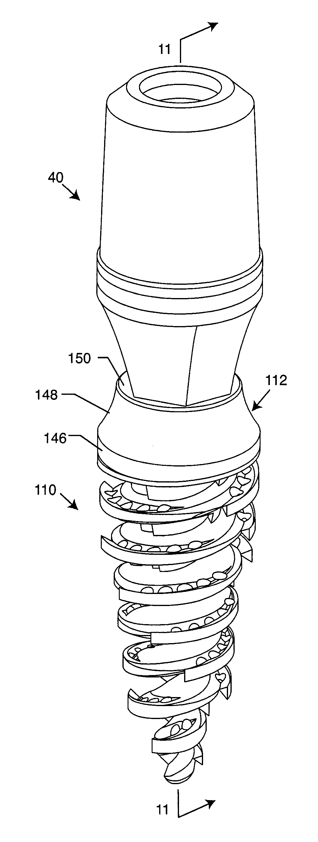
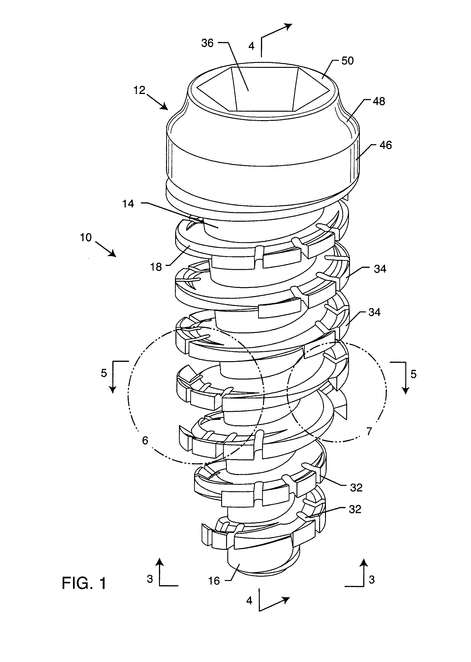
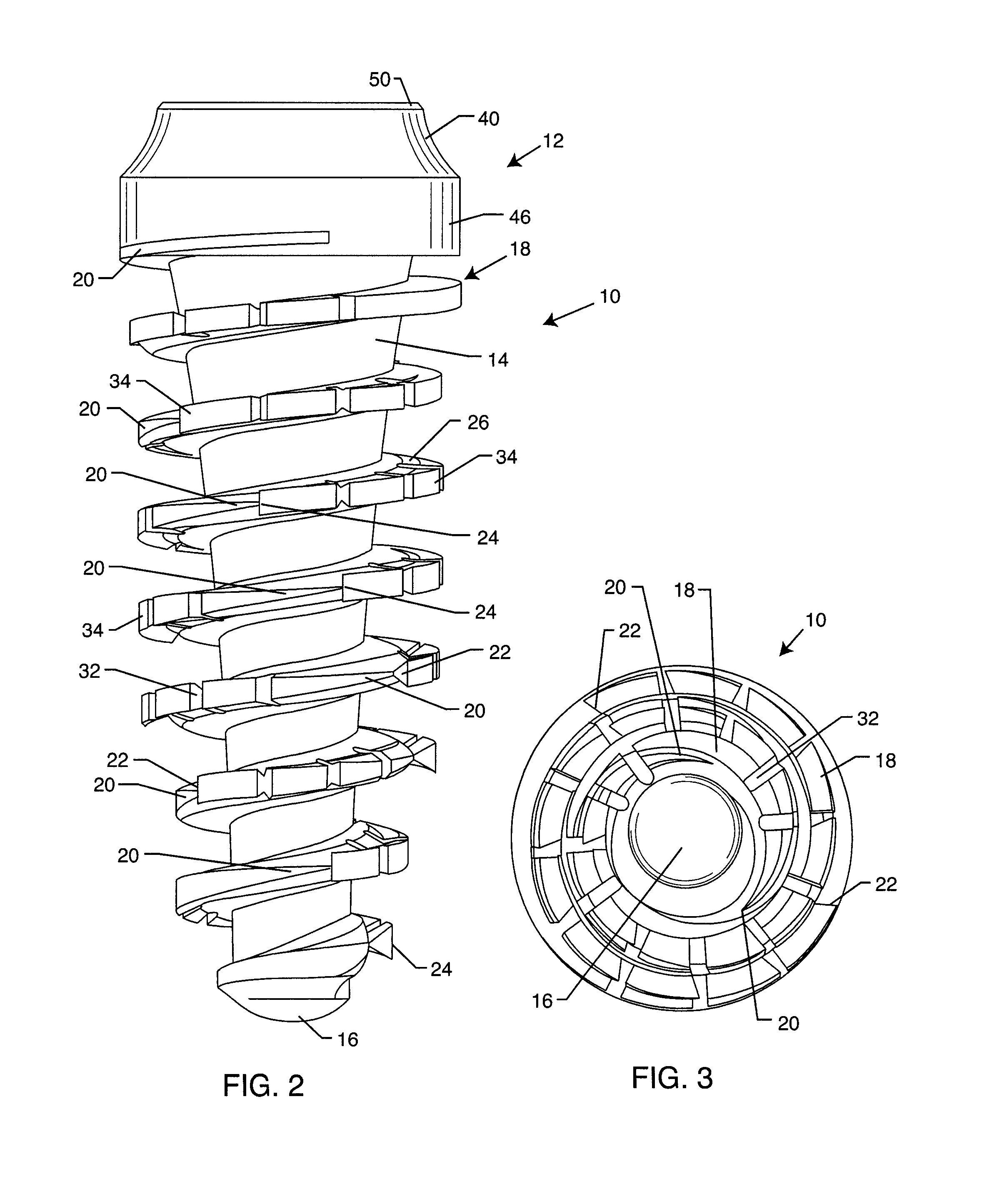
[0064]As shown in the accompanying drawings, for purposes of illustration, the present invention resides in a self-osteotomizing and grafting implant. As will be more fully described herein, the osteotomy is achieved by the implant 10 itself as it is being driven into place. The bone shavings from the osteotomy are collected around the implant 10 as it is seated and act as autogenous bone graft, filling in the voids of the implant structure and implant bone surfaces. Moreover, the implant 10 has both vertical as well as lateral stabilization due to its design, responsible for the macro-osseointegration feature of the implant.

[0065]In existing implant designs, the bone next to the implant is condensed and crushed to achieve initial stability. In the prior art, during the initial osteotomy, the bone is brought out to the surface by the twist drills and suctioned away with the irrigating solution. Once the implant is inserted, any voids or vents within the implant space are filled with...


PUM


Abstract

A bone implant includes a head and a core body extending from the head to a tip. An osteotomy blade extends outwardly from at least a portion of the core body to form a spiral thread. Channels form bone cutting edges of the implant. The implant, and particularly the osteotomy blade, is configured to self-osteotomize and direct cut bone into the channels to facilitate bone growth and grafting and integration of the implant to the bone.

Description

RELATED APPLICATION[0001]This application is a continuation-in-part of U.S. patent application Ser. No. 13 / 946,509, filed Jul. 19, 2013, which is a continuation-in-part of U.S. patent application Ser. No. 13 / 553,678, filed Jul. 19, 2012, which claims priority to U.S. Provisional Application No. 61 / 510,009, filed Jul. 20, 2011.BACKGROUND OF THE INVENTION[0002]The present invention generally relates to bone implants, such as dental implants. More particularly, the present invention is directed to a self-osteotomizing and self-grafting bone implant which creates its own osteotomy and facilitates bone growth and integration of the implant.[0003]Traditionally, orthopedic medicine and dentistry have copied older established industries, like carpenters, to create fasteners for prosthetic items to be attached directly to bone in the form of various cone screws. In such non-medical, inanimate industries, as in cases of wood, plastic or metal, the principal of direct fasteners is based upon c...

Claims


Application Information

Patent Timeline
IPC IPC(8): A61C8/00
CPCA61C8/0025A61C8/0022A61C8/0024A61C8/006A61C8/0068A61C8/0069A61B17/863
Inventor ZADEH, PARSA T.
Owner ZADEH PARSA T
Learn More