
Selective water vapour transport membranes comprising a nanofibrous layer and methods for making the same

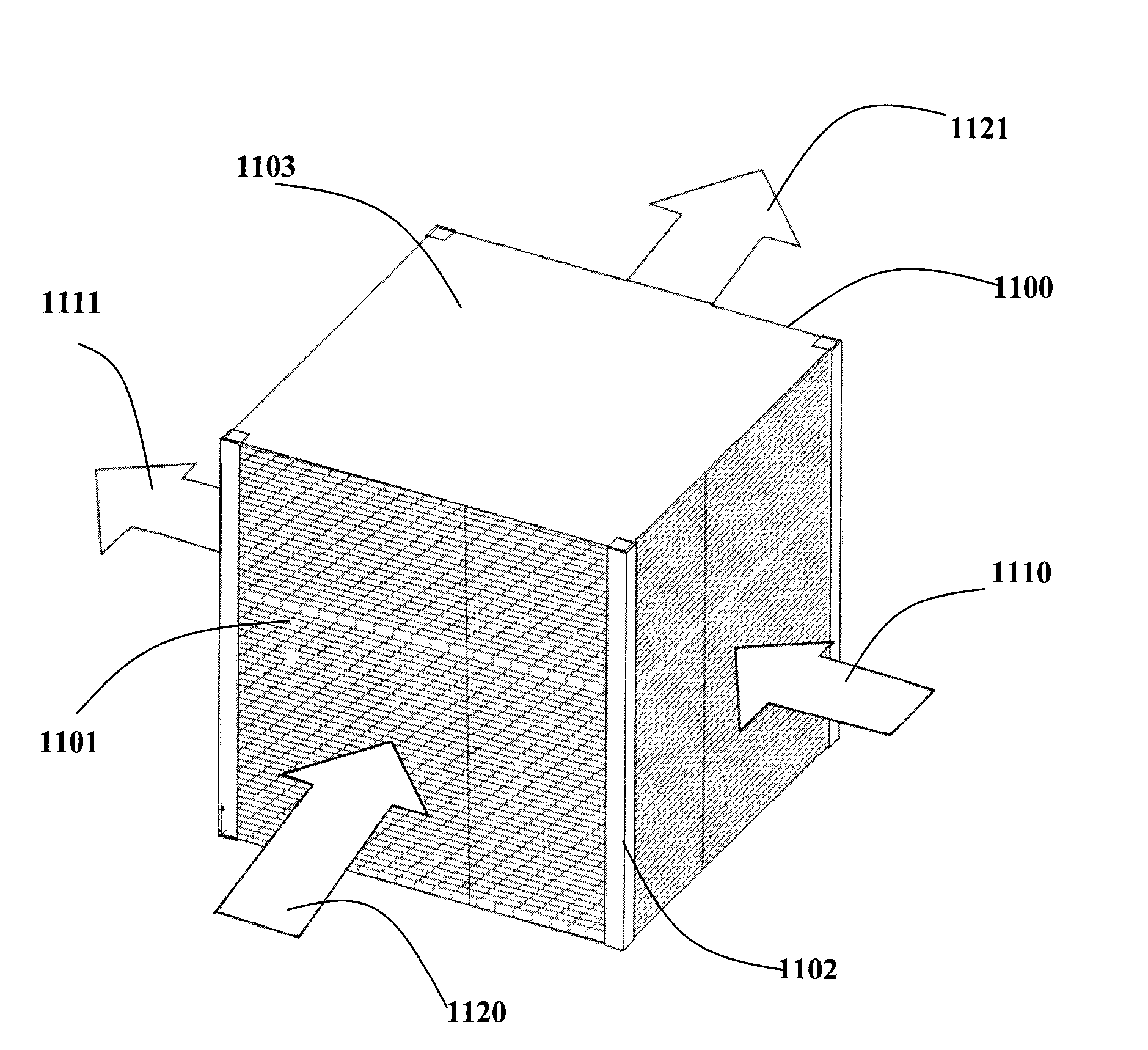
a technology of selective water vapour and transport membrane, which is applied in the manufacture of textile/flexible products, domestic heating details, heat recovery systems, etc., can solve the problems of waste of energy, sickness, absenteeism and productivity loss, waste of useable energy, etc., and achieves high water vapour permeability, thin membrane, and low cost

Active Publication Date: 2014-10-30
CORE ENERGY RECOVERY SOLUTIONS INC
View PDF3 Cites 30 Cited by
  • Summary
  • Abstract
  • Description
  • Claims
  • Application Information

AI Technical Summary

Benefits of technology

This patent is about a new type of membrane that can transport water vapor. The membrane is made using a special layer made of nanofibers, which makes it highly permeable and selective for gas-to-gas moisture and heat transfer applications. This membrane is low-cost and can be used in a thin form for combined heat and moisture transport applications. It can also be made on various support structures, which can improve the performance of the gas exchanger.

Problems solved by technology

For example, in hot and humid climates, useable energy is wasted when the cooled air from the building is exhausted.
If buildings tend to be too humid, ERVs can lower humidity levels, reducing the likelihood of mould, bacteria, viruses, and fungi which cause sickness, absenteeism and lost productivity.
On the other hand, in cold dry climates, energy is wasted when warm air from the building is exhausted, plus there can be an additional issue of the incoming air stream being too dry.
However, in many cases there is crossover contamination (leakage between streams) due to leakage at seals or joints in the ERV and / or due to passage of the gases through the membrane material.
For example, cellulose films are not mechanically and dimensionally stable in wet conditions, tend to be subject to freeze / thaw cracking, and are typically fairly thick (for example, greater than 10 micron) which leads to lower water permeance.
Cellulose films and coated papers also tend to be flammable and subject to microbial growth.
Such membranes tend to be costly and their fabrication involves the use of organic solvents and other harsh chemicals.
Also, the types of additives that can be incorporated are limited by the chemistry involved.
Laminated membranes made by bonding a cast ionomer film to a porous support, or a blown film (for example, polyether-block amide (PEBA)) laminated to a nonwoven tend to delaminate because of the different dimensional properties (for example, swelling and thermal expansion) of the two layers and the difficulty in creating a strong bond between them.
Also, the water transport performance of such laminated membranes tends to be limited because the ionomer or blown film has to be sufficiently thick (for example, greater 5 microns) so that it can be processed into a continuous, pinhole-free film and then handled in order to manufacture the laminate.
For example, materials which have low air permeability tend to also have low water permeability; polymer films provide excellent handling, but tend to be rather flammable; and specialty polymers and highly engineered thin film composites and similar materials tend to be very expensive.
However, many higher permeability polymers are cost prohibitive for these applications.
For example in one current generation membrane material for ERV applications, the cost of the microporous substrate layer is over 80% of the membrane cost.

Method used


Image

  • Selective water vapour transport membranes comprising a nanofibrous layer and methods for making the same
  • Selective water vapour transport membranes comprising a nanofibrous layer and methods for making the same
  • Selective water vapour transport membranes comprising a nanofibrous layer and methods for making the same

Examples


experimental examples

Example 1

Supported Nanofibrous Layers Compared to Known Microporous Substrates

[0114]Various microporous substrates were compared to uncoated, supported nanofibrous layers. A microporous polypropylene substrate was obtained from Celgard LLC, under the name Celgard 2500; the thickness was 25 micron, the average pore size was 0.204×0.054 micron (average dimension about 0.13 micron) and the porosity was 55%. A microporous silica-polyethylene membrane, was obtained from ENTEK International; the thickness was 191 micron, the average pore size was 0.065 micron, and the porosity was 63%.

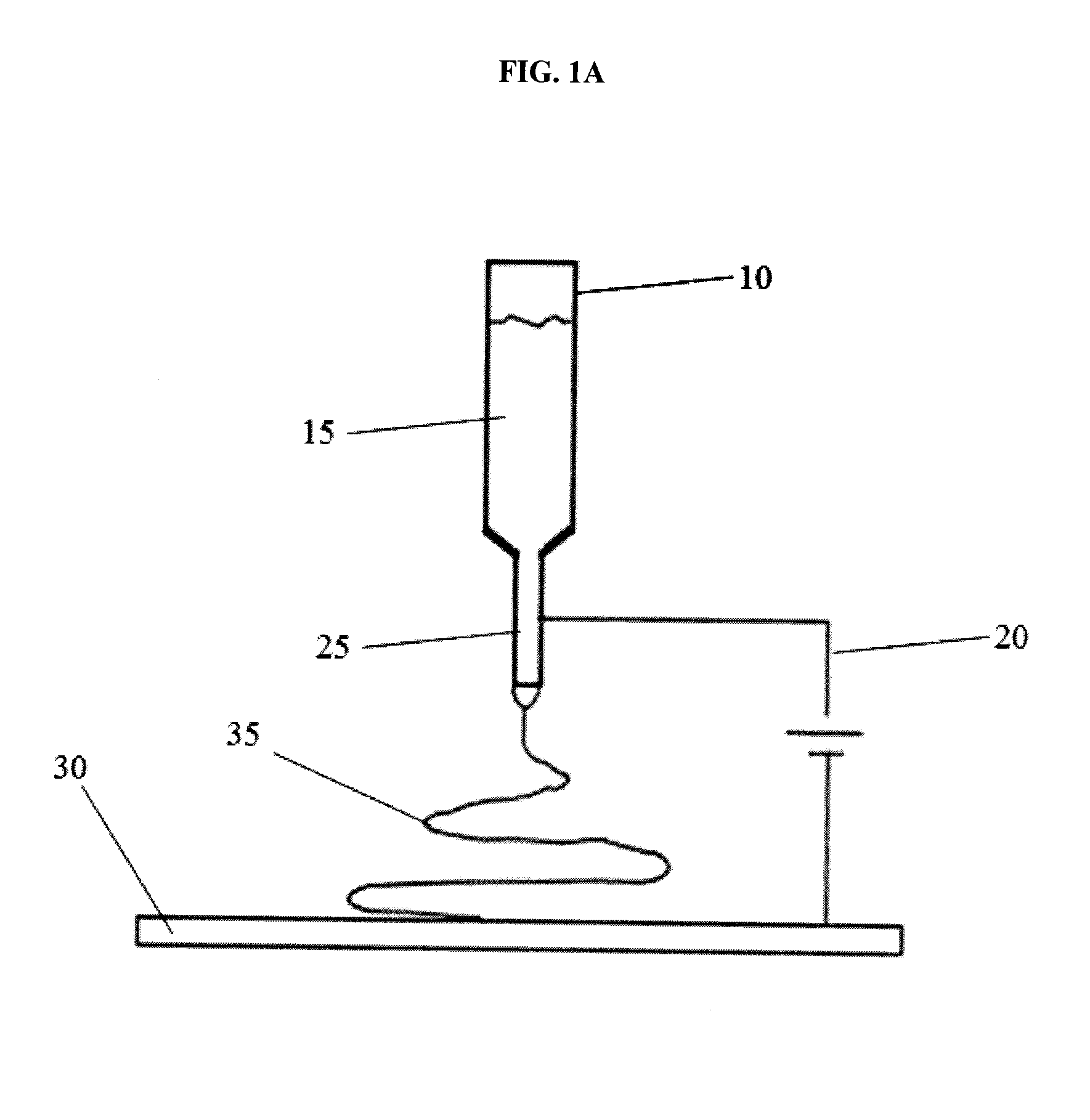
[0115]A non-woven support layer, polyester non-woven (Reemay 2004 / 2006), 1 oz / sq. yd. was obtained from Fiberweb. Polyacrylonitrile (PAN) was obtained from Scientific Polymer Products with an average molecular weight of 150 000 g / mol. A solution of 10% weight PAN in dimethylformamide (DMF) was created under stirring at 70° C. The PAN solution was placed in a 10 mL syringe with an eighteen gauge hypodermic ne...

example 2

Coating of Supported PAN Nanofibrous Layers with PEO-PU

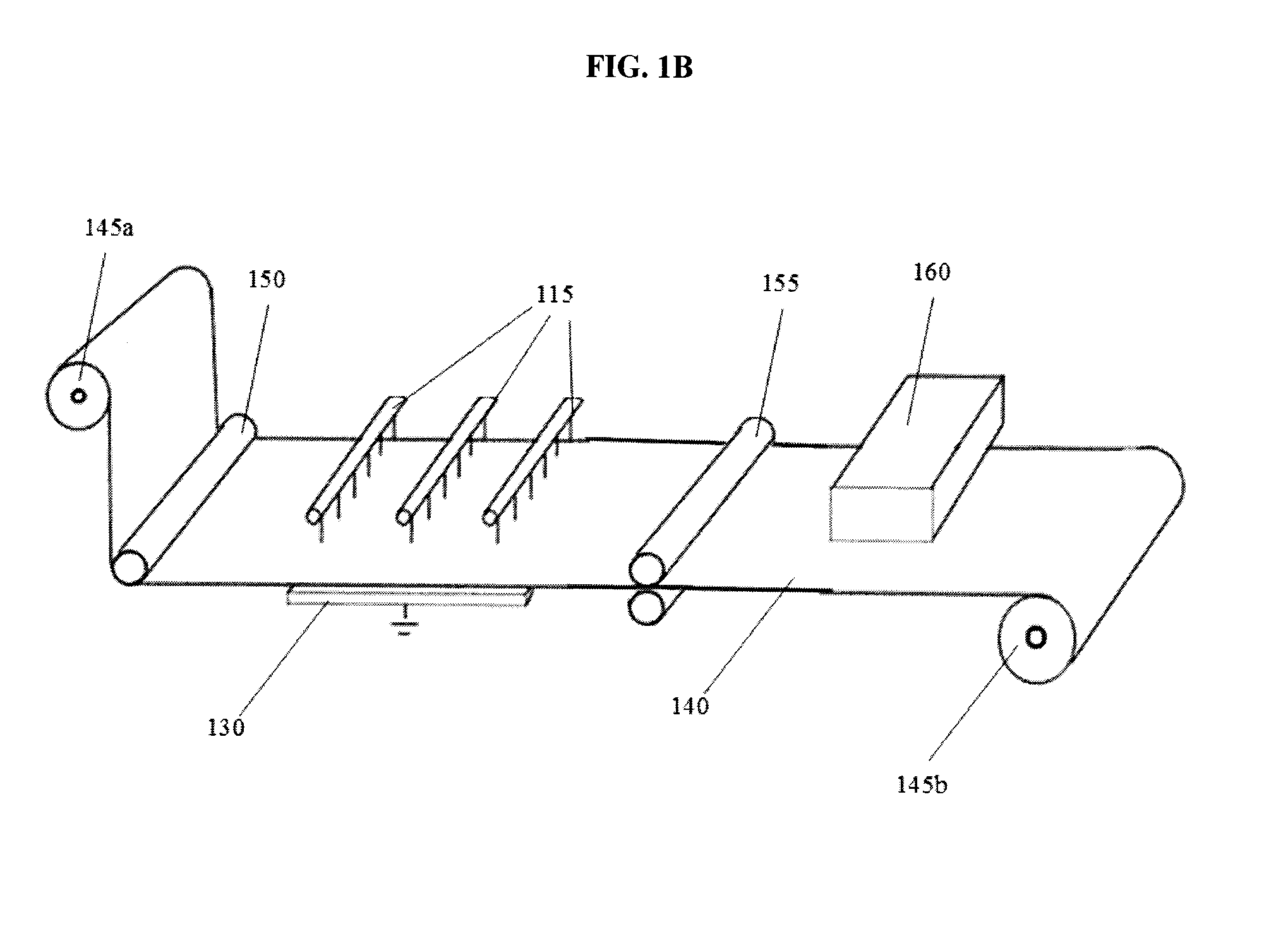
[0117]In order to make the supported nanofibrous materials selective, a dense polymer coating layer can be applied to the nanofibrous layer. Polyether-polyurethanes are known to be effective dense polymer layers, imparting high selectivity for water vapour over other gases, and offering high water vapour permeability. Polyacrylonitrile nanofibrous layers were electro-spun on to a polyester non-woven support layer in a method similar to that described in Example 1. The polyester non-woven (30 cm×80 cm) support was attached to a grounded collector target which was a rotating belt. The belt was rotated at a speed of 1.5 m / min. Nanofibrous mats were deposited on the non-woven supports at 3 levels of nanofibre loading—test results for the three samples are shown in TABLE 2. The porosity of all three samples is quite high—greater than 90% in the test performed.

TABLE 2SpinningThicknessPorositySampleTime (mins)(μm)(%)#2A608>90#2B9012>90...

example 3

Coating of Supported PAN Nanofibrous Layer with PFSA

[0121]Membranes comprising coated supported nanofibrous layers as fabricated in Example 3 demonstrated improved water vapour permeation performance over conventional membranes comprising coated microporous substrates, while maintaining sufficient selectivity. However, the water vapour permeance was considerably lower than that of the uncoated, supported nanofibrous layers described in Example 1. Decreasing the loading of the functional coating or increasing the water vapour permeability of the functional coating is thus desirable.

[0122]One method by which to increase the permeance of the final membrane would be to use a functional polymer with a higher water vapour permeability than the polyether-polyurethane polymers used in Example 3. There are many polymers with higher permeability than polyether-polyurethanes, as discussed above. Sulphonated polymers are one such class of polymers—many of these have high water vapour permeabili...


PUM

PropertyMeasurementUnit
Diameteraaaaaaaaaa
Nanoscale particle sizeaaaaaaaaaa
Thicknessaaaaaaaaaa

Abstract

A water vapour transport membrane comprises a nanofibrous layer disposed on a macroporous support layer, the nanofibrous layer coated with a water permeable polymer. A method for making a water vapour transport membrane comprises forming a nanofibrous layer on a macroporous support layer and applying a water permeable polymer to the nanofibrous layer. The water permeable polymer can be applied for so that the nanofibrous layer is substantially or partially filled with the water permeable polymer, or so that the coating forms a substantially continuous layer on one surface of the nanofibrous layer. In some embodiments of the method, the nanofibrous layer is formed by electro-spinning at least one polymer on at least one side of the porous support layer. In some embodiments, the support layer is formable and the method further comprises forming a three-dimensional structure from the water vapour transport membrane, for example, by compression molding, pleating or corrugating.

Description

CROSS-REFERENCE TO RELATED APPLICATIONS[0001]This application is related to and claims priority benefits from U.S. Provisional Patent Application Ser. No. 61 / 494,122, entitled “Selective Water Vapour Transport Membranes Comprising a Nanofibrous Layer and Methods for Making the Same”, filed on Jun. 7, 2011, which is hereby incorporated by reference in its entirety.FIELD OF THE INVENTION[0002]The present invention relates to water vapour transport membranes comprising a nanofibrous layer and selective coating. Such membranes are particularly suitable for use in enthalpy exchangers and other applications involving exchange of moisture and optionally heat between gas streams, with little or no mixing of the gas streams through the membrane.BACKGROUND[0003]A heat recovery ventilator (HRV) is a mechanical device that incorporates a heat exchanger with a ventilation system for providing controlled ventilation into a building. The heat exchanger heats or cools the incoming fresh air using t...

Claims


Application Information

Patent Timeline
IPC IPC(8): F24F12/00B29D99/00
CPCB29D99/005F24F12/001B01D53/228B01D69/10B01D71/32B01D71/36B01D71/42B01D71/52B01D71/54B01D71/82B01D2323/30B01D2323/39B01D2257/80B01D2259/4508D01D5/0076D01F6/18B01D2325/48F24F12/006B01D53/268B32B5/022B32B5/26B32B15/02B32B15/20B32B1/00B32B3/28B32B2260/023B32B2260/046B32B2262/0276B32B2307/7242Y02B30/56Y02P70/62B01D71/421B01D69/1071B01D69/106B01D71/5211B01D53/22B01D2053/221
Inventor HUIZING, RYAN NICHOLASKO, FRANK K.
Owner CORE ENERGY RECOVERY SOLUTIONS INC
Learn More