
Device for indirectly cooling battery module of eco-friendly vehicle

a battery module and indirect cooling technology, applied in the direction of batteries, lighting and heating apparatus, electrochemical generators, etc., can solve the problems of deteriorating the efficiency and stability of the battery, insufficient heat emission or heat diffusion to the outside of the battery, and expansion of the electrode in the battery, so as to maximize the heat emission performance of the battery and improve the adherence

Active Publication Date: 2014-10-30
HYUNDAI MOTOR CO LTD
View PDF8 Cites 27 Cited by
  • Summary
  • Abstract
  • Description
  • Claims
  • Application Information

AI Technical Summary

Benefits of technology

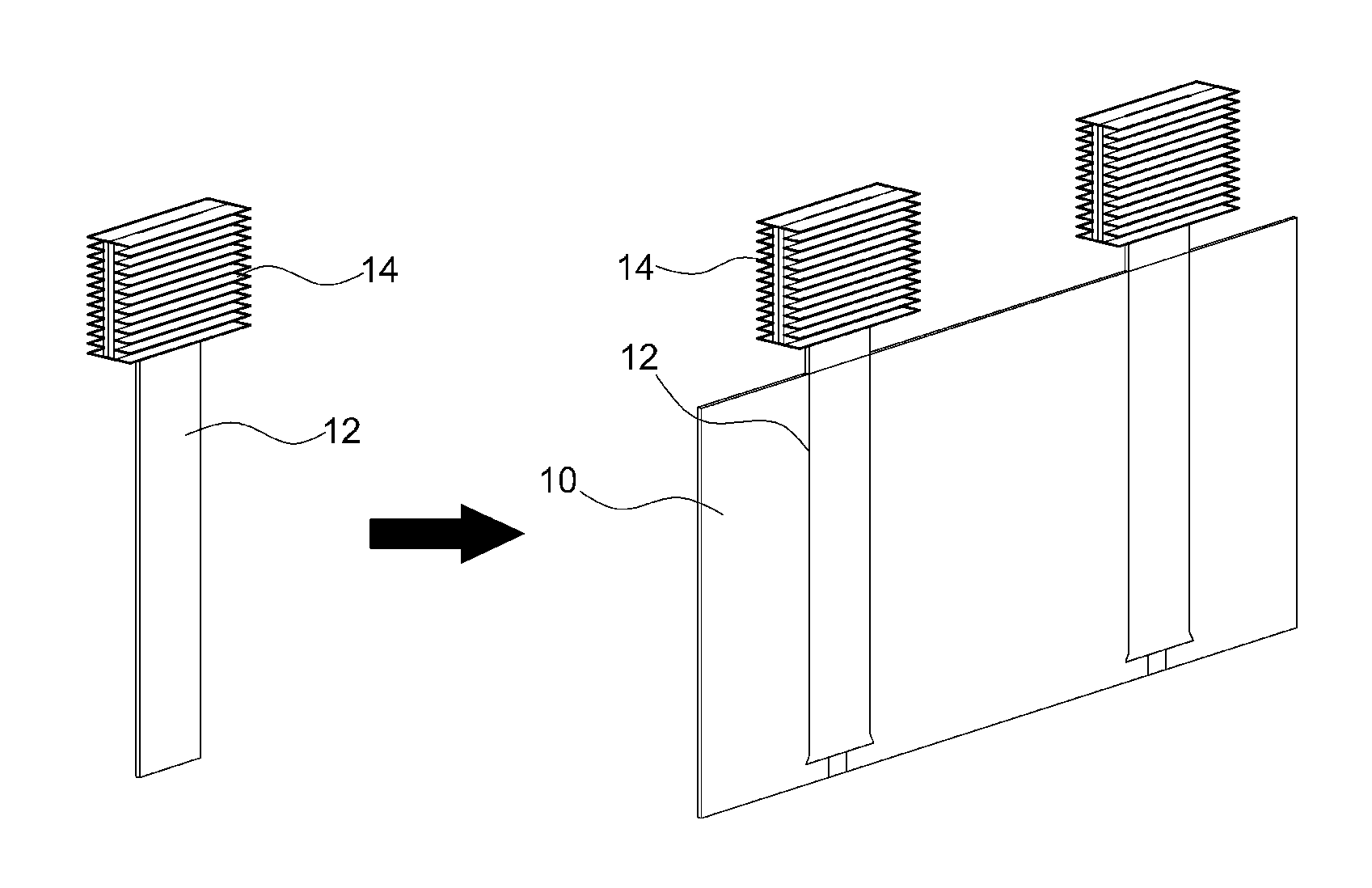
The present invention provides a device for cooling an eco-friendly vehicle's battery module. The device includes a heat-conductive interfacial plate that is closely placed between battery cells and a heat sink that is connected to the heat pipe. The heat-conductive interfacial plate improves heat-emission performance and prevents leakage of the battery cells. Additionally, a planar heat emitter is placed between battery cells to heat the battery to proper levels in cold start and low-temperature environments. The device includes a heat emitter that is close-contact with the battery cells and is protected with a liquid silane resin surface hardener. The technical effects of this invention include maximizing battery performance, preventing degradation of vehicle power, and ensuring safety during battery charging and discharging.

Problems solved by technology

For a battery of an electric vehicle, a local temperature difference may be generated between battery cells due to heat generated by fast charging, high power, the number of times of repetitive charging, or the like, or a thermal runaway may occur which deteriorates the battery's efficiency and stability.
These phenomena are known as occurring since heat emission or heat diffusion to the outside the battery is insufficient when compared to heat generated inside the battery.
A pouch-type battery cell undergoes a change in volume due to intercalation and deintercalation of lithium ions into electrode materials during charging and discharging, causing potential damage in a separator between two electrode materials as well as expansion of electrodes in the battery.
The damage in the separator causes battery performance degradation and battery final capacity reduction as well as internal resistance generation, and thus, a heat-emission interfacial material for coping with battery volume expansion is required.
When the pouch-type battery expands significantly, a polymer pouch may be damaged and thus internal electrolyte may leak and gas may be discharged.
Since a pouch-type cell module is configured by stacking several cells, when expansion or gas emission or explosion occurs, direct damage may occur to neighboring cells.
However, such a technique may not handle volume expansion of a battery (e.g., a pouch-type battery) due to fast charging / discharging.
In addition, a flat panel type heat pipe applied in another embodiment of the conventional examples directly contacts the surface of the battery, causing a potential tear in the pouch type battery by metallic burr generated in heat pipe manufacturing during vehicle's vibration or battery module assembly.
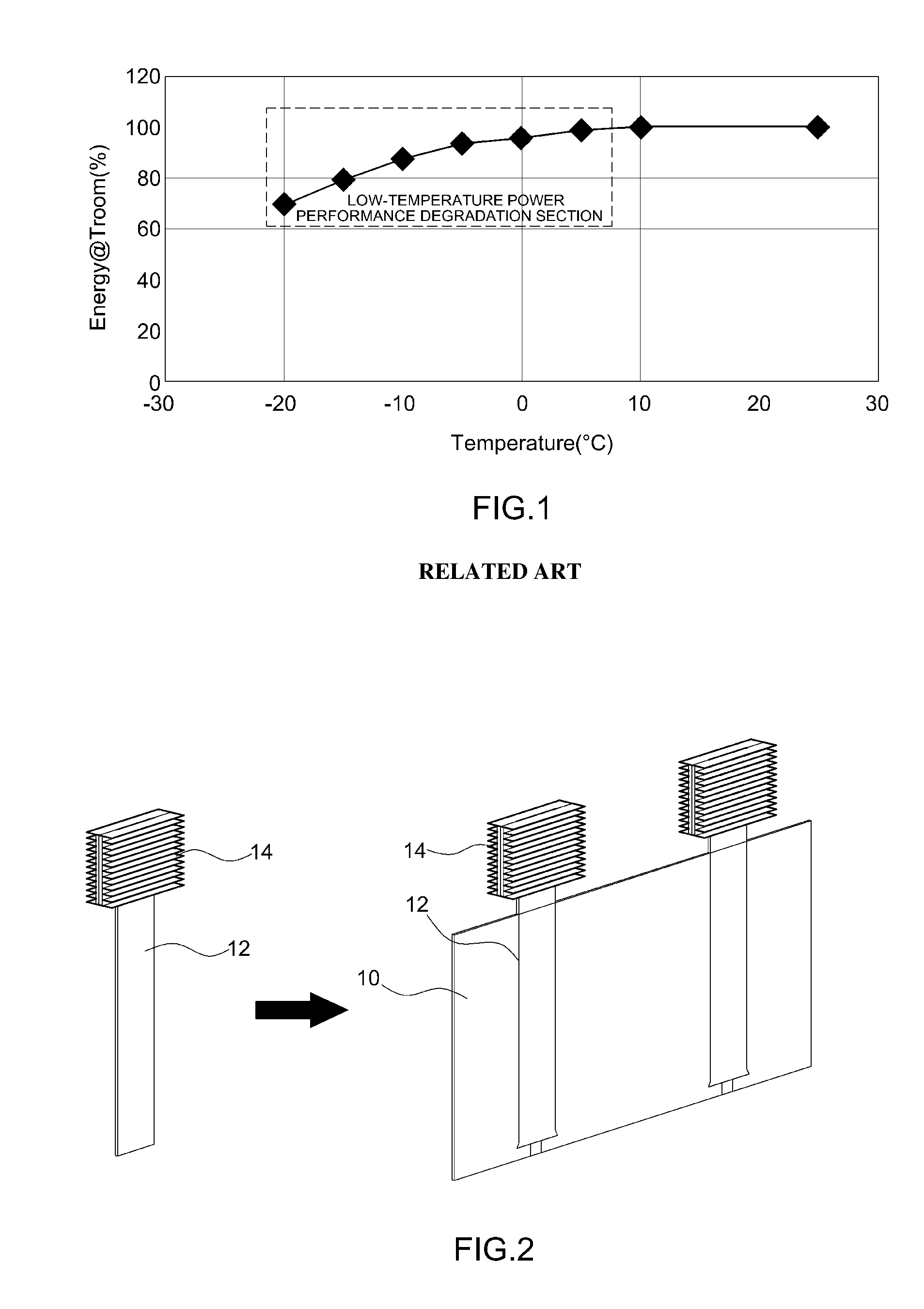
Moreover, another disadvantage of a conventional battery module is that a material or a device is not provided to cope with cold start of the vehicle or power degradation in a low-temperature environment.

Method used


Image

  • Device for indirectly cooling battery module of eco-friendly vehicle
  • Device for indirectly cooling battery module of eco-friendly vehicle
  • Device for indirectly cooling battery module of eco-friendly vehicle

Examples


Embodiment Construction

[0027]It is understood that the term “vehicle” or “vehicular” or other similar term as used herein is inclusive of motor vehicles in general such as passenger automobiles including sports utility vehicles (SUV), buses, trucks, various commercial vehicles, watercraft including a variety of boats and ships, aircraft, and the like, and includes hybrid vehicles, electric vehicles, plug-in hybrid electric vehicles, hydrogen-powered vehicles, fuel cell vehicles, and other alternative fuel vehicles (e.g., fuels derived from resources other than petroleum). As referred to herein, a hybrid vehicle is a vehicle that has two or more sources of power, for example both gasoline-powered and electric-powered vehicles.

[0028]The terminology used herein is for the purpose of describing particular embodiments only and is not intended to be limiting of the invention. As used herein, the singular forms “a”, “an” and “the” are intended to include the plural forms as well, unless the context clearly indic...


PUM

PropertyMeasurementUnit
thicknessaaaaaaaaaa
thicknessaaaaaaaaaa
temperaturesaaaaaaaaaa

Abstract

A device for indirectly cooling a battery module of an eco-friendly vehicle is provided that cools the battery module using an interfacial plate into which a heat pipe is inserted to maximize battery heat emission performance and simultaneously prevent degradation of battery performance. A thermally-conductive interfacial plate in which a heat pipe is embedded by over-molding is disposed between battery cells and a heat sink, which is a condensation unit, integrally connected to an upper end of the heat pipe is disposed in a cooling air flow path to improve contact strength between the interfacial plate and the battery cells. A planar heat emitter is disposed between the battery cells where the interfacial plate is not disposed to heat the battery to a proper-level temperature in a cold-start environment and a low-temperature environment, thereby improving battery performance and preventing degradation in vehicle power.

Description

CROSS-REFERENCE TO RELATED APPLICATION[0001]This application claims under 35 U.S.C. §119(a) the benefit of Korean Patent Application No. 10-2013-0046449 filed on Apr. 26, 2013, the entire contents of which are incorporated herein by reference.BACKGROUND[0002](a) Technical Field[0003]The present disclosure relates to a device for indirectly cooling a battery module of an eco-friendly vehicle, and more particularly, to a device for indirectly cooling a battery module of an eco-friendly vehicle, that indirectly cools the battery module using an interfacial plate into which a heat pipe is inserted, to maximize battery heat emission performance and simultaneously, prevent degradation of battery performance.[0004](b) Background Art[0005]Eco-friendly vehicles refer to electric vehicles, fuel-cell vehicles, or the like which generate no emissions, and in the eco-friendly vehicles, batteries are mounted to drive motors for driving a vehicle. Since the reliability and stability of a battery s...

Claims


Application Information

Patent Timeline
Patent Type & Authority Applications(United States)
IPC IPC(8): H01M10/6557H01M10/625H01M10/613
CPCH01M10/5059H01M2220/20H01M10/5016H01M10/5004F28D15/0275F28D2021/0028H01M10/613H01M10/625H01M10/6552H01M10/6557Y02E60/10B60K11/00F01P3/00H01M10/60
Inventor KWAK, JIN WOOHAN, DO SUCKLEE, GUN GOOSONG, KYONG HWAKANG, HYUKSEO, JEONG HUN
Owner HYUNDAI MOTOR CO LTD
Learn More