Ejection volume correction method for inkjet head, ejection volume correction apparatus
a technology of ejection volume and inkjet head, which is applied in the direction of mechanical measurement arrangement, photomechanical apparatus, instruments, etc., can solve the problem of not being able to achieve uniform film thickness between substrates, and achieve uniform film thickness and film thickness uniform
- Summary
- Abstract
- Description
- Claims
- Application Information
AI Technical Summary
Benefits of technology
Problems solved by technology
Method used
Image


Examples
first embodiment
Method of Correcting Ejection Volume: First Embodiment
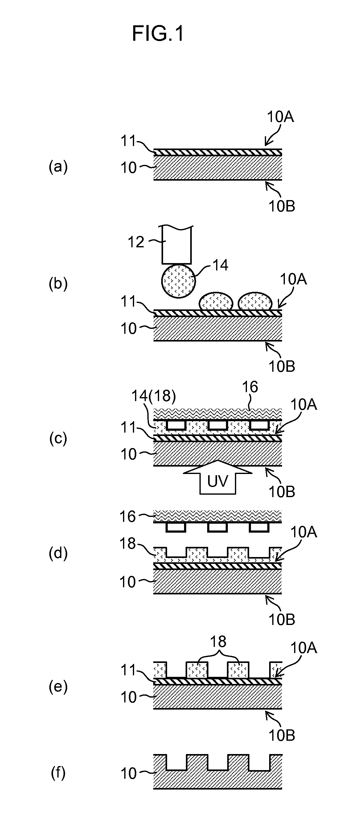
[0074]As described above, a concavoconvex pattern formed in a mold 16 is transferred to the photocurable resin film 18. In the subsequent ashing step, it is necessary for the thickness of the photocurable resin film 18 to be uniform, in order that the ashing conditions are kept uniform between substrates at all times. In other words, it is necessary for the droplets 14 ejected from the inkjet head to have a uniform volume.
[0075]However, the volume of the droplets 14 ejected from the inkjet head changes with variation in the viscosity of the resin material between different batches of resin. Consequently, this gives rise to variation in the thickness of the photocurable resin film 18 between substrates. Furthermore, a similar problem also occurs when the inkjet head is replaced. In order to resolve this problem, the ejection volume of the inkjet head should be corrected so as to remain uniform, each time the batch of resist materi...
second embodiment
[0132]In the first embodiment, droplets are ejected from all of the nozzles onto one region, but in the present embodiment, droplets are ejected onto different regions for each nozzle.
[0133]FIG. 10 is a schematic drawing showing a substrate for film thickness measurement (substrate 120) relating to the present embodiment, and an inkjet head 320 which arranges functional ink droplets on the substrate 120 by ejecting functional inks while moving by means of a scanning device (not illustrated).
[0134]32 regions 122-1, 122-2, 122-3, 122-4, 124-1, . . . , 136-3 and 136-4 are set on the front surface of the substrate 120 so as to correspond to the regions of the mold described below.
[0135]The inkjet head 320 is composed so as to be capable of performing a scanning action in X and Y directions over the front surface of the substrate 120 by means of a scanning device (not illustrated). 8 nozzles n1 to n8 which eject functional ink are arranged in one direction in the lower surface of the ink...
third embodiment
[0146]In the present embodiment, when actually carrying out nano-imprinting, the ejection volume is corrected by measuring the ejection velocity. Here, the table 500 in the first embodiment is created in advance and is stored on the storage device, such as a memory.
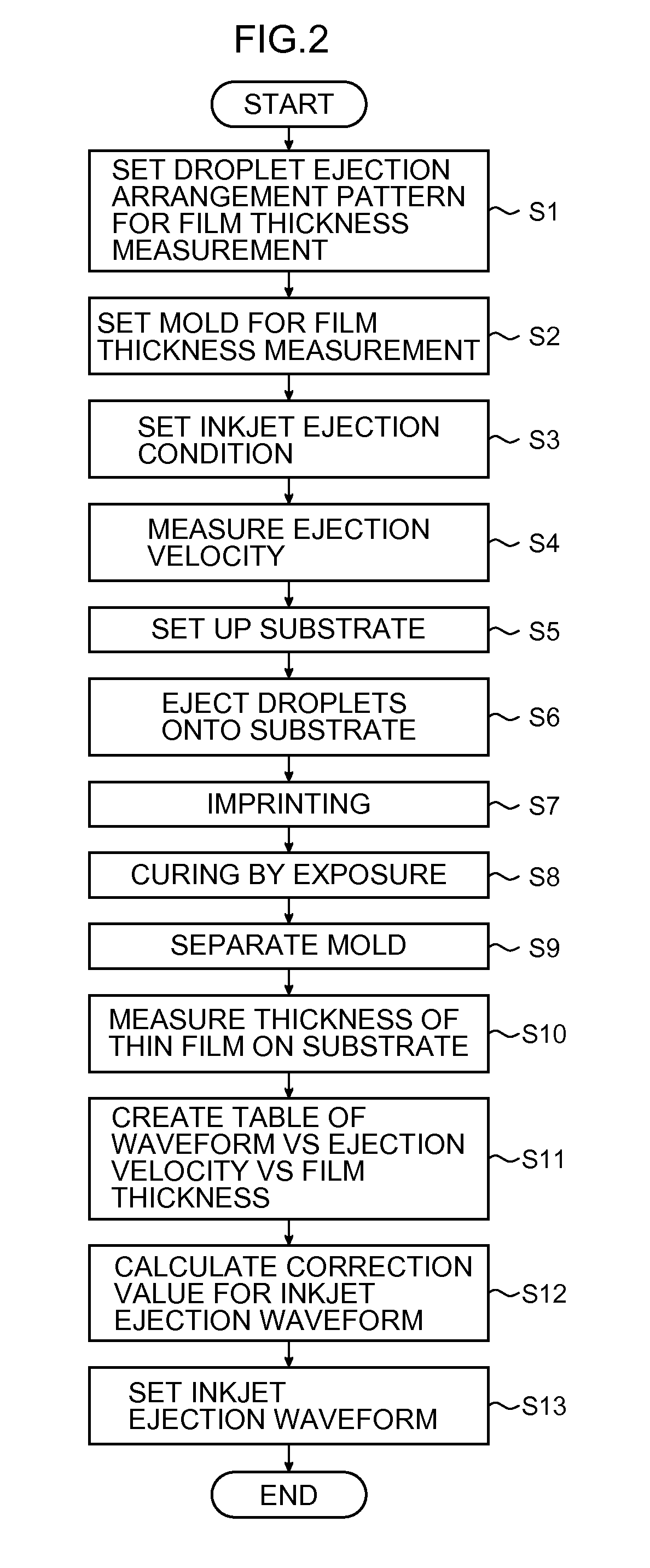
[0147]FIG. 13 is a flowchart showing a method of correcting an inkjet ejection volume relating to the present embodiment.
[0148]Firstly, a droplet ejection arrangement pattern is set based on pattern information for the mold used (step S21). The mold used here is a mold for actually carrying out nano-imprinting, rather than a mold for film thickness measurement.
[0149]Next, the inkjet ejection conditions are set (step S22). Here, the ejection conditions should be set provisionally.
[0150]Subsequently, ink droplets are ejected by the respective ejection waveforms (drive voltages), from each nozzle, and the ejection velocity is measured (step S23).
[0151]Thereupon, the ejected droplet volume corresponding to the desired film th...
PUM
| Property | Measurement | Unit |
|---|---|---|
| Thickness | aaaaa | aaaaa |
| Diameter | aaaaa | aaaaa |
| Volume | aaaaa | aaaaa |
Abstract
Description
Claims
Application Information
 - R&D
- Intellectual Property
- Life Sciences
- Materials
- Tech Scout
- Unparalleled Data Quality
- Higher Quality Content
- 60% Fewer Hallucinations
Browse by: Latest US Patents, China's latest patents, Technical Efficacy Thesaurus, Application Domain, Technology Topic, Popular Technical Reports.
© 2025 PatSnap. All rights reserved.Legal|Privacy policy|Modern Slavery Act Transparency Statement|Sitemap|About US| Contact US: help@patsnap.com