Vacuum vapor deposition apparatus
a vacuum vapor and apparatus technology, applied in vacuum evaporation coatings, brushes, coatings, etc., can solve the problems of increasing the size of the evaporation source, increasing the effort of arranging the crucibles, and increasing the cost of the system
- Summary
- Abstract
- Description
- Claims
- Application Information
AI Technical Summary
Benefits of technology
Problems solved by technology
Method used
Image
Examples
first embodiment
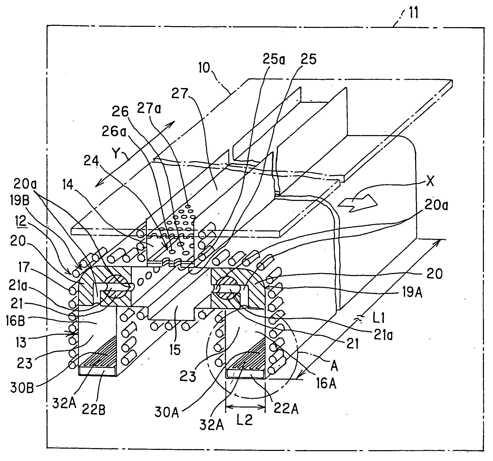
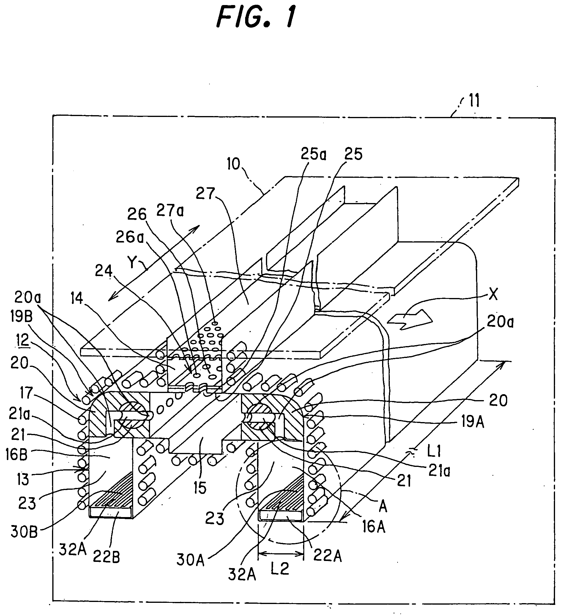
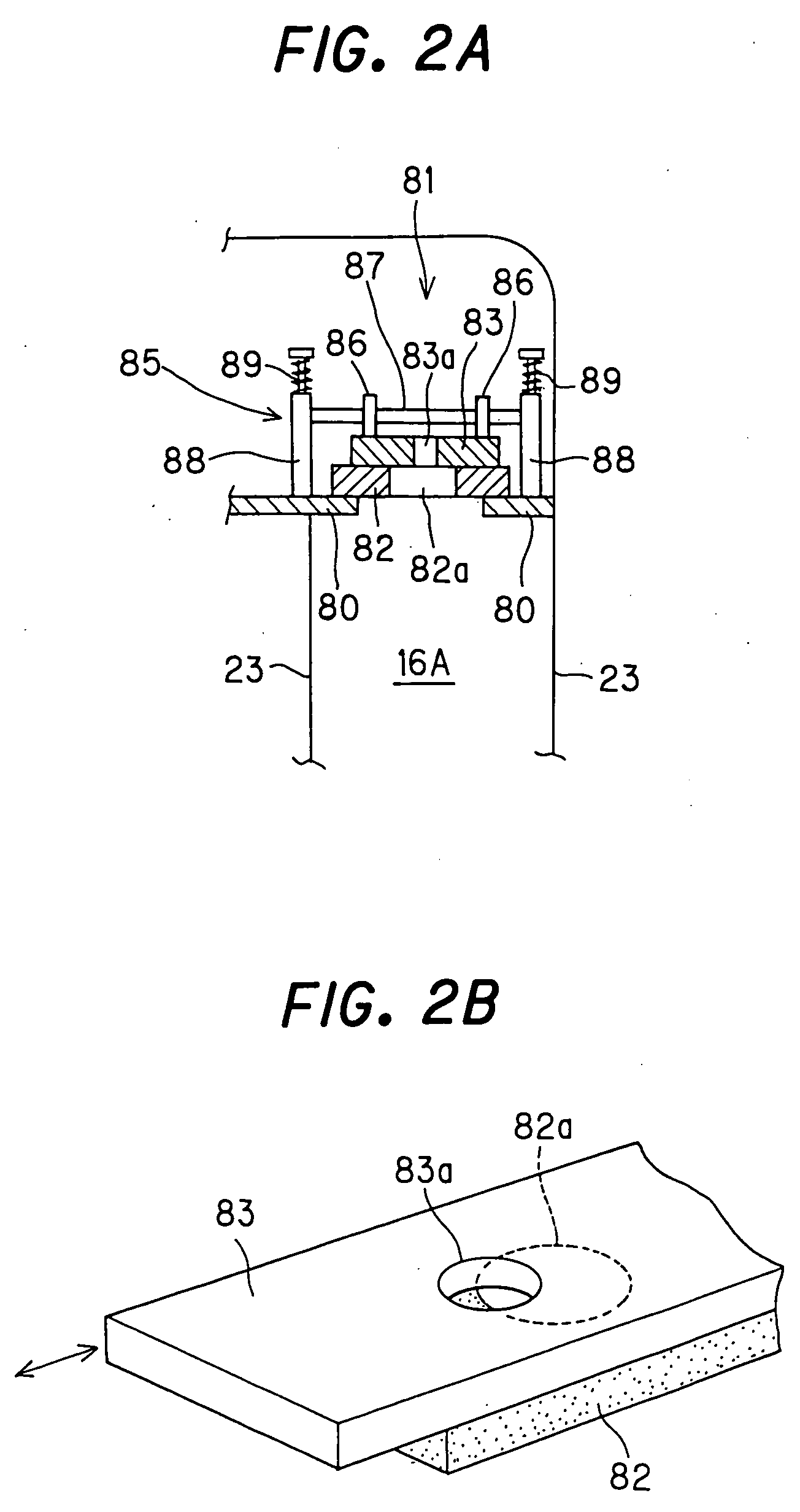
[0060]FIG. 1 is a perspective view illustrating the construction of a vacuum vapor deposition apparatus according to a first embodiment of the present invention. FIG. 3 is an enlarged perspective view of part A of FIG. 1. FIG. 4A is a cross-sectional view (plan view of a crucible) as seen from the direction of arrows B of FIG. 3. FIG. 4B is an enlarged cross-sectional view taken along the line C-C of FIG. 4A. It should be noted that FIGS. 2A and 2B are views illustrating another example of the construction of a spool shutter in the vacuum vapor deposition apparatus of the first embodiment.
[0061] As illustrated in FIG. 1, the vacuum vapor deposition apparatus of the first embodiment includes a main system 12 of an vapor deposition apparatus and a substrate transport system (not shown) in a vacuum chamber 11 and is intended for co-deposition and organic EL. The main system 12 serves as an evaporation source. The substrate transport system is provided above the main system 12.
[0062] ...
second embodiment
[0084]FIG. 7 is a perspective view illustrating the construction of an essential part of a vacuum vapor deposition apparatus according to a second embodiment of the present invention. FIG. 8 is a cross-sectional view (plan view of electric heaters) as seen from the direction of arrows D of FIG. 7. FIG. 9 is a flowchart for explaining temperature control.
[0085] In the vacuum vapor deposition apparatus of the second embodiment which is illustrated in FIGS. 7 and 8, electric heaters 41 are further provided as heating means in the crucible 22A for a dopant material in the vacuum vapor deposition apparatus of the first embodiment. Though not illustrated, the crucible 22B for a host material also has a construction in which electric heaters 41 are provided as in the crucible 22A. Except for the above, the construction (the overall construction and arrangement of the crucibles, the overall construction of the vacuum vapor deposition apparatus, and the like) of the vacuum vapor deposition ...
third embodiment
[0092]FIG. 12 is a perspective view illustrating the construction of an essential part of a vacuum vapor deposition apparatus according to a third embodiment of the present invention. FIG. 13A is a cross-sectional view (plan view of a crucible) as seen from the direction of arrows E of FIG. 12. FIG. 13B is an enlarged cross-sectional view taken along the line F-F of FIG. 13A.
[0093] As illustrated in FIGS. 12 to 13B, in the vacuum vapor deposition apparatus of the third embodiment, instead of slit grooves, holes 51 are provided in the surface 31 of the crucible 22A for the dopant material in the vacuum vapor deposition apparatus of the aforementioned first embodiment. Although not shown, the crucible 22B for the host material also has a construction in which holes 51 are provided as in the crucible 22A. Except for the above, the construction (the arrangement of the crucibles, the overall construction of the vacuum vapor deposition apparatus, and the like) of the vacuum vapor deposit...
PUM
| Property | Measurement | Unit |
|---|---|---|
| Temperature | aaaaa | aaaaa |
| Length | aaaaa | aaaaa |
Abstract
Description
Claims
Application Information
 - R&D
- Intellectual Property
- Life Sciences
- Materials
- Tech Scout
- Unparalleled Data Quality
- Higher Quality Content
- 60% Fewer Hallucinations
Browse by: Latest US Patents, China's latest patents, Technical Efficacy Thesaurus, Application Domain, Technology Topic, Popular Technical Reports.
© 2025 PatSnap. All rights reserved.Legal|Privacy policy|Modern Slavery Act Transparency Statement|Sitemap|About US| Contact US: help@patsnap.com


