
Multi-abrasive tool

a multi-abrasive and tool technology, applied in the field of manufacturing abrasives, can solve the problems of reducing the removal efficiency, affecting the quality of the surface finish, and the friction developed by the abrasion also produces a lot of heat, so as to achieve the complexity of the abrasive tool, reduce the number, and the effect of increasing the complexity

Active Publication Date: 2014-06-05
MA VA SRL
View PDF1 Cites 16 Cited by
  • Summary
  • Abstract
  • Description
  • Claims
  • Application Information

AI Technical Summary

Benefits of technology

The present invention provides abrasive tools with improved polishing efficiency and reduced wear and tear. The arrangement of abrasive elements in the roughness sequences helps to improve polishing in proximity to walls. The use of small manual tools for artistic or artisanal work allows for grinding curved surfaces while selecting the appropriate part of the tool. Additionally, the higher complexity of the abrasive tools reduces the number of passages and saves on dead times, resulting in increased speed of the entire polishing or grinding process.

Problems solved by technology

The friction developed by the abrasion also produces a lot of heat, which facilitates undesired chemical reactions.
The largest grains allow obtaining a greater removal efficiency, but negatively affect the quality of the surface finish, while the finest grains allow obtaining surfaces of improved quality, but with lower removal efficiency.
In the manual polishing machines, it is the machine itself to be moved, and since the polishing process requires the aforesaid sequential steps, carried out with increasingly finer grain abrasives, the overall duration of the process will increase the dead times necessary for changing the abrasive tools.
The conventional grinding process also requires a change of tools with decreasing grain size, and thus has the drawbacks of the polishing, although to a lesser extent.

Method used


Image

  • Multi-abrasive tool
  • Multi-abrasive tool
  • Multi-abrasive tool

Examples


Embodiment Construction

[0066]In the following description, equivalent elements which appear in different figures can be indicated with the same symbols. In the illustration of one figure, it is possible to make reference to elements not expressly indicated in that figure but in preceding figures. The scale and the proportions of the various depicted elements do not necessarily correspond with the actual scale and proportions.

[0067]FIG. 17 shows an abrasive tool 50 constituted by a centrally-perforated discoid support 51, made of material suitable for the type of abrasive material employed and for the technique used for fixing the abrasive powder. If the tool 50 is a diamond tool, the support 51 could be, for example: brass, aluminum, resinoid material, vegetable or artificial fiber, etc. On the support 51, the abrasive powder, starting from the external edge, forms ten concentric circular rings 52-61 of equal width, contiguous to each other, made of different size grains. The finest grain is present on th...


PUM


Abstract

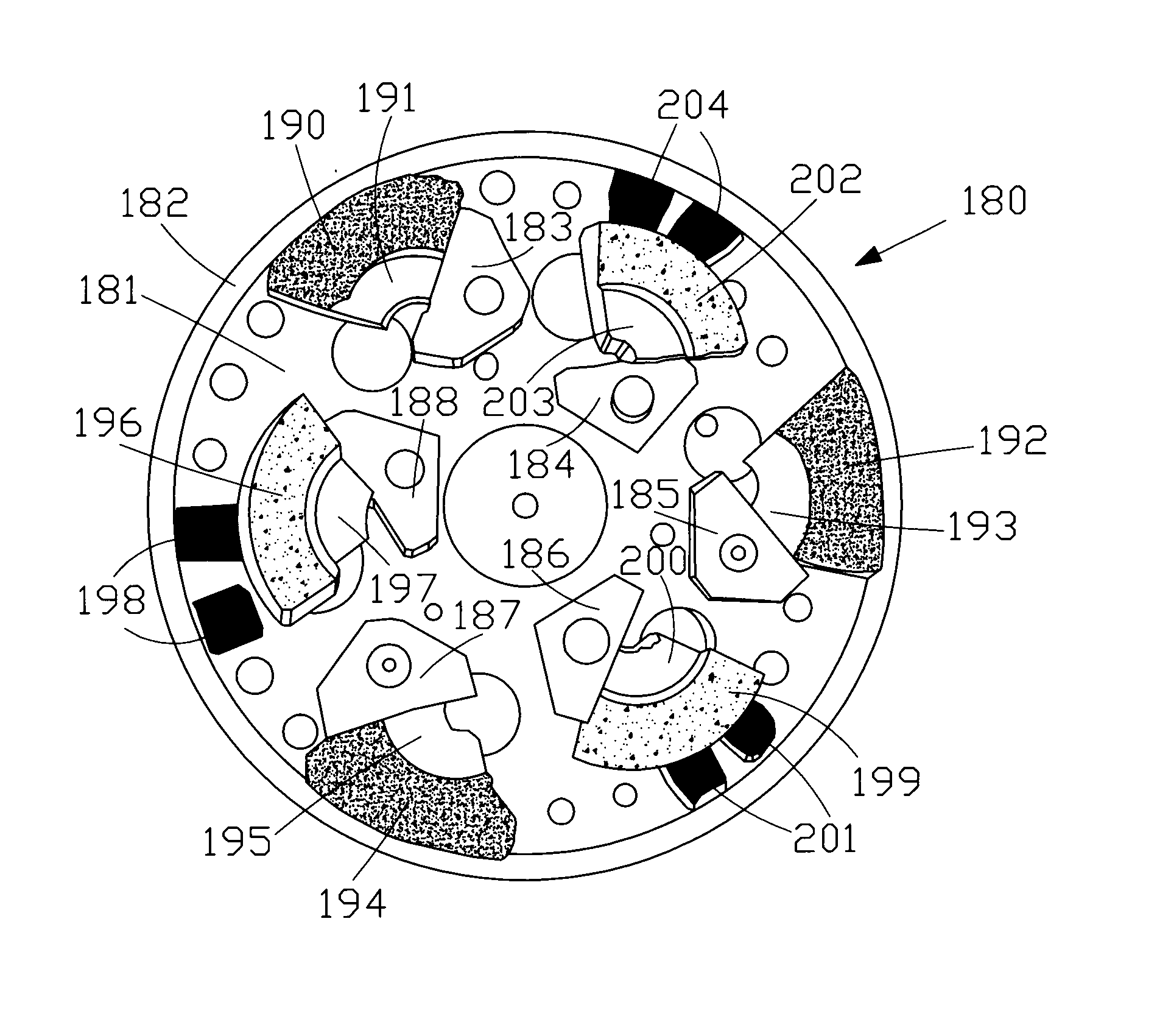
A multi-abrasive tool is constituted by a support on which abrasive elements are present. Such abrasive elements are arranged in a manner so as to form one or more paths along which the successive abrasive elements have grain size sequentially increasing or decreasing by an arbitrary quantity when passing from on element to the next. Such principle gives rise to abrasive tools with different conformation both for polishing machines and for grindstones. For roto-orbital and planetary polishing machines, and optionally orbital, such support is circular and the grain sequence is circumferential, or radial, or in both directions. A first tool is constituted by contiguous (or non-contiguous) circular rings, that are differently abrasive. A second tool comprises differently abrasive elements arranged along the circular peripheral edge. A third tool comprises differently abrasive elements arranged along a spiral path of 360° starting from the edge. A fourth tool comprises two 180° spiral paths with reversed roughness sequences. A fourth tool comprises pairs of differently abrasive small cylinders fixed to a plate on concentric circumferences. A fifth tool is obtained directly on the plate of the polishing machine by means of reliefs and spacers for fixing differently abrasive sectors. For linear polishing machines, the abrasive support is a belt along which differently abrasive rectangular or oblique zones follow each other. For alternative polishing machines, the abrasive support is a plate shaped like the aforesaid belt. For tools to use with grindstones, the multi-abrasive element has a cylindrical rotation symmetry, or conical with rounded tip, or spherical symmetry.

Description

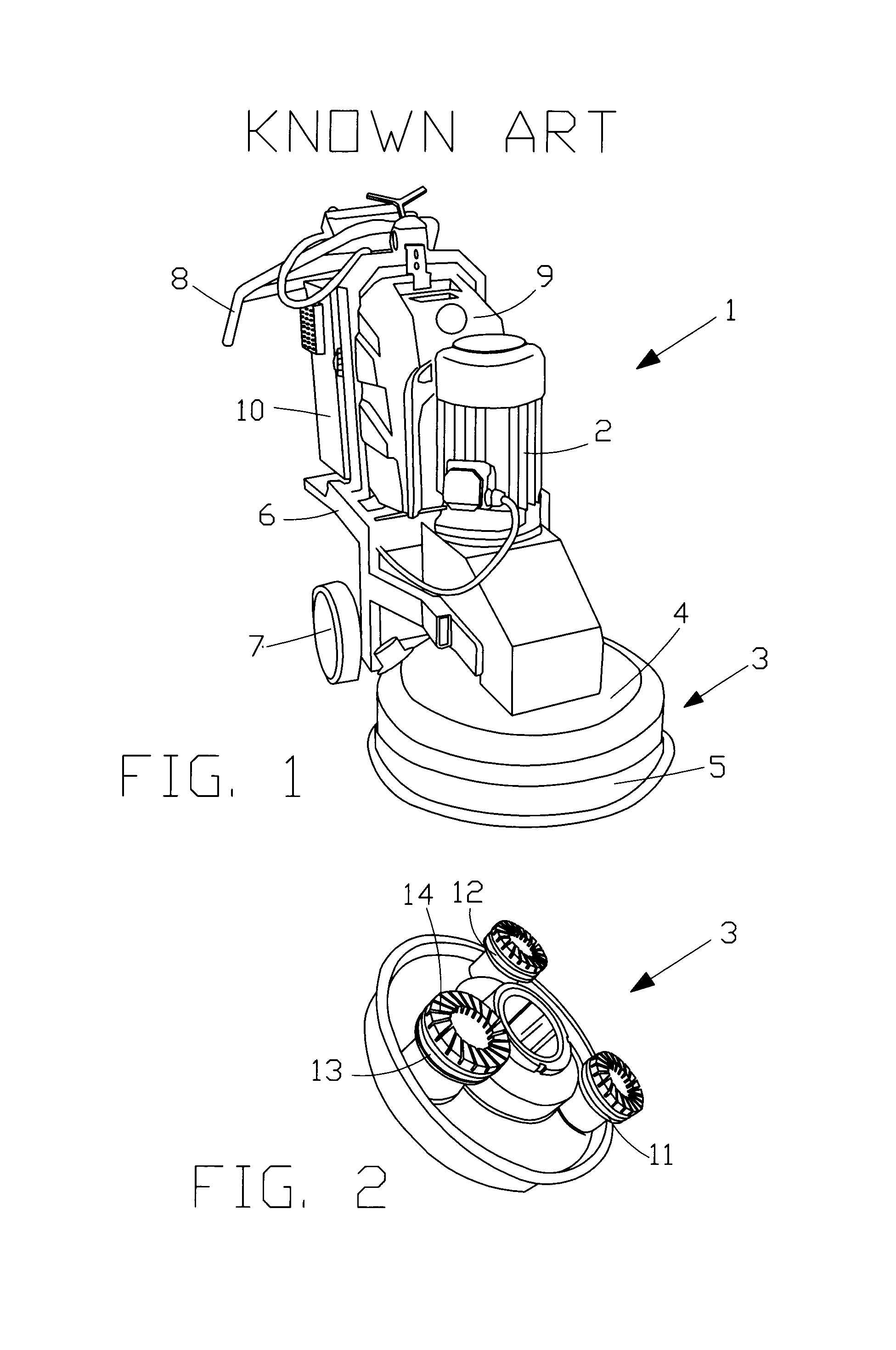
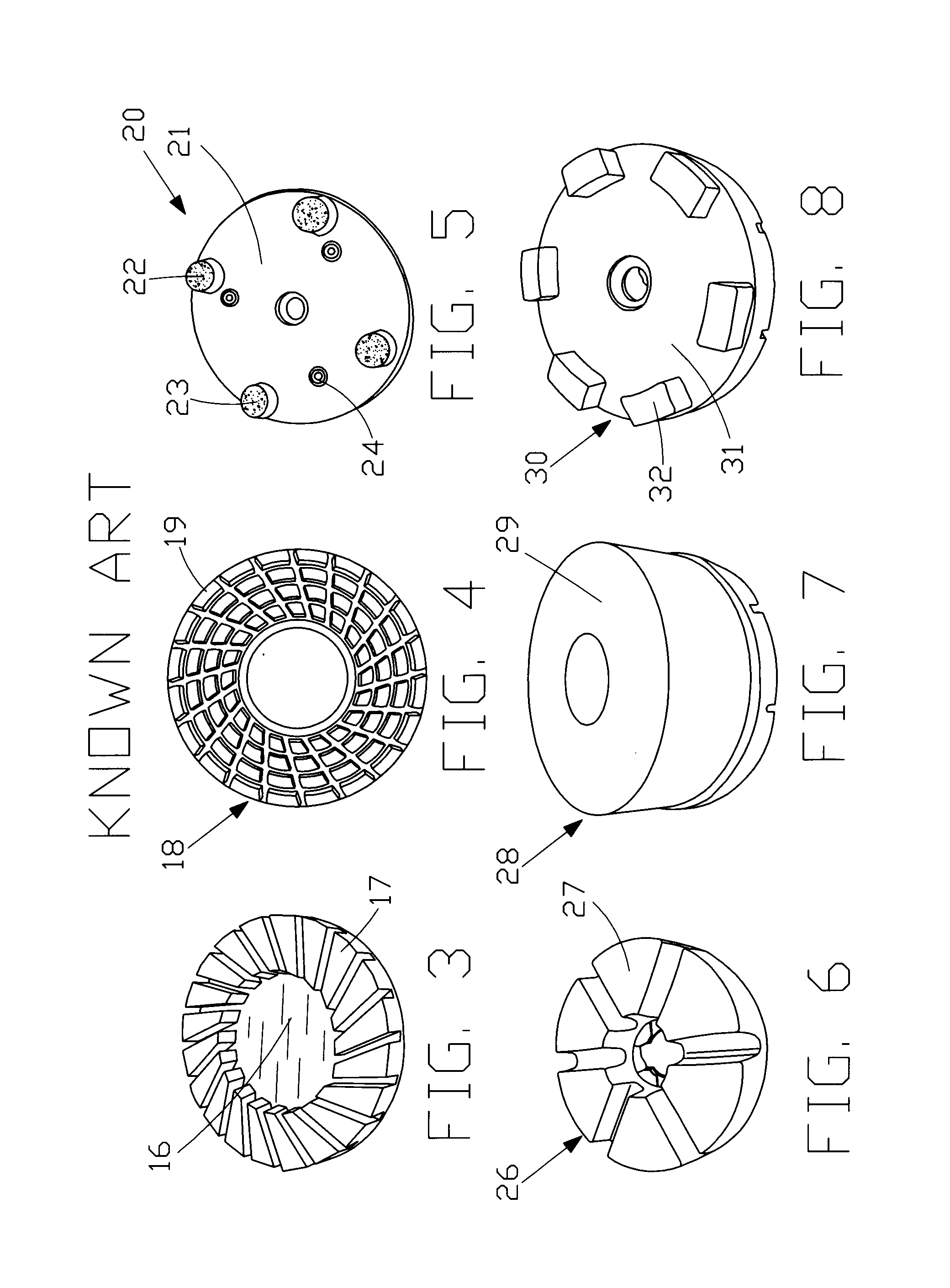
FIELD OF APPLICATION OF THE INVENTION[0001]The present invention is applied to the manufacture of abrasive tools for the polishing of surfaces of various materials with rough surfaces, such as for example: stone, concrete, metal, wood, and more precisely to a multi-abrasive tool. The invention is applicable to the development of planar abrasive tools for polishing machines of any type, as well as for tools with cylindrical symmetry for grindstones. Polishing machines that could potentially use the abrasive tool of the present invention are, for example, those which use an abrasive paper belt rotating on two axes; those which use an abrasive vibrating in a straight line; those with abrasive single-disc with simple rotation; orbital polishing machines which use an abrasive to which an orbital vibratory movement is imparted with respect to its own axis (which does not rotate on itself); roto-orbital polishing machines in which, unlike the orbital machines, the axis also rotates on itse...

Claims


Application Information

Patent Timeline
IPC IPC(8): B24D7/14B24D11/04
CPCB24D5/14B24D7/06B24D7/14B24D11/04
Inventor FIORE, NICOLA
Owner MA VA SRL
Learn More