
Method of manufacturing laser welded steel pipe

a technology of laser welding and steel pipe, which is applied in the field of manufacturing a steel pipe, can solve the problems of difficulty in cold district use of oil country tubular goods or a line pipe employing electric resistance welding steel pipe, and poor low-temperature toughness of seam, etc., and achieves stab manufacturing, excellent quality, and no reduction in weld efficiency

Active Publication Date: 2014-05-08
JFE STEEL CORP
View PDF9 Cites 14 Cited by
  • Summary
  • Abstract
  • Description
  • Claims
  • Application Information

AI Technical Summary

Benefits of technology

The present invention allows for the manufacturing of high-quality laser welded steel pipes without compromising weld efficiency. These pipes have excellent low-temperature toughness and corrosion resistance, making them suitable for use in oil country tubular goods, line pipes, and cold environments. Additionally, there will be no spattering or undercuts in the weld portion, resulting in a seam that is highly effective.

Problems solved by technology

Such a seam has a problem of poor low-temperature toughness.
Thus, oil country tubular goods or a line pipe employing an electric resistance welded steel pipe is difficult to use in a cold district.
The reason why such a seam has poor low-temperature toughness is because, while edges are being welded together, the high-temperature molten metal reacts with atmospheric oxygen and forms an oxide, which is likely to remain in the seam.
The electric resistance welded steel pipe has another problem in that the corrosion resistance of the seam is likely to be reduced because an alloy element in the molten metal is likely to segregate while the edges are being welded together.
Thus, oil country tubular goods or line pipes employing electric resistance welded steel pipes are difficult to use in a severe corrosion environment (for example, sour environment).
The scattered spatter adheres to welding equipment, thereby degrading the quality of the seam.
Concurrently, the spatter also adheres to the optical component, making the welding operation unstable.
Since laser welding is performed by converging high-density heat energy, a large amount of spatter is formed, causing welding defects such as occurrence of undercut or underfill (or depression).
Reduction of laser power or defocusing, however, not only leads to reduction of welding speed (i.e., reduction of weld efficiency) but also involves a problem of making lack of penetration more likely to occur.
Thus, such a technology involves not only reduction of weld efficiency but also a problem of making lack of penetration more likely to occur.
Furthermore, since prisms that divide laser beams are expensive, the cost of the welding operation inevitably increases.
Thus, an appropriate filler wire has to be selected in accordance with the components of open pipes, thereby increasing the burden of stock management of filler wires or production control of laser welding.
This technology, however, makes the structure of welding equipment complex, thereby increasing the burden of not only maintenance but also management of the welding operation.
With this technology, however, welding defects are not reduced during laser welding performed under conditions in which stress occurs in a weld portion (under conditions such as where stress occurs in a molten weld pool due to the weld portion of an electric resistance welded steel pipe receiving an upset).

Method used


Image

  • Method of manufacturing laser welded steel pipe
  • Method of manufacturing laser welded steel pipe
  • Method of manufacturing laser welded steel pipe

Examples


example

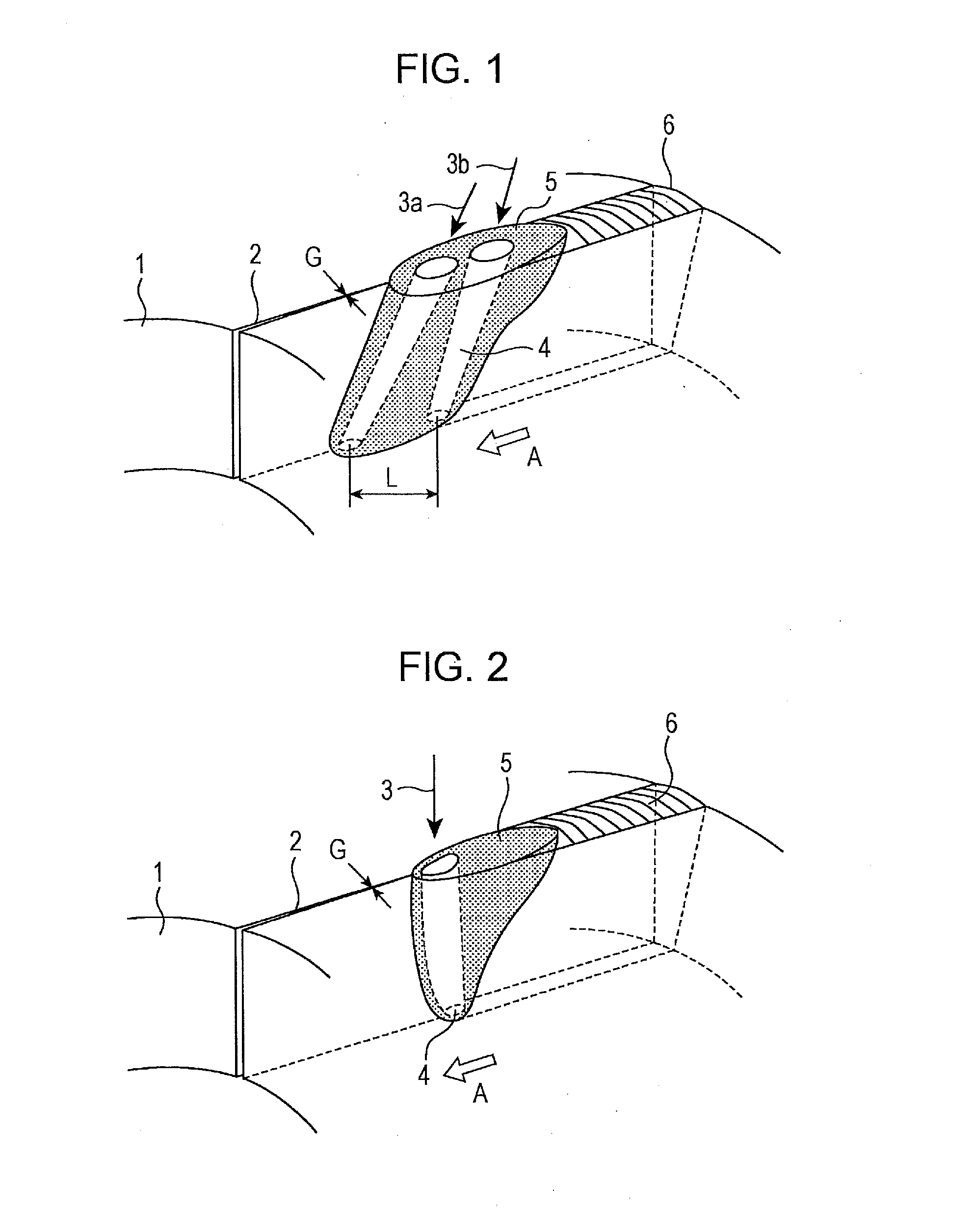
[0062]Laser welded steel pipes were manufactured by forming steel strips into cylindrical open pipes using forming rolls, pressing the edges of the open pipes using squeeze rolls, and emitting two laser beams from the upper surface side of the open pipes as illustrated in FIG. 1. Components of the steel strips are shown in Table 1.

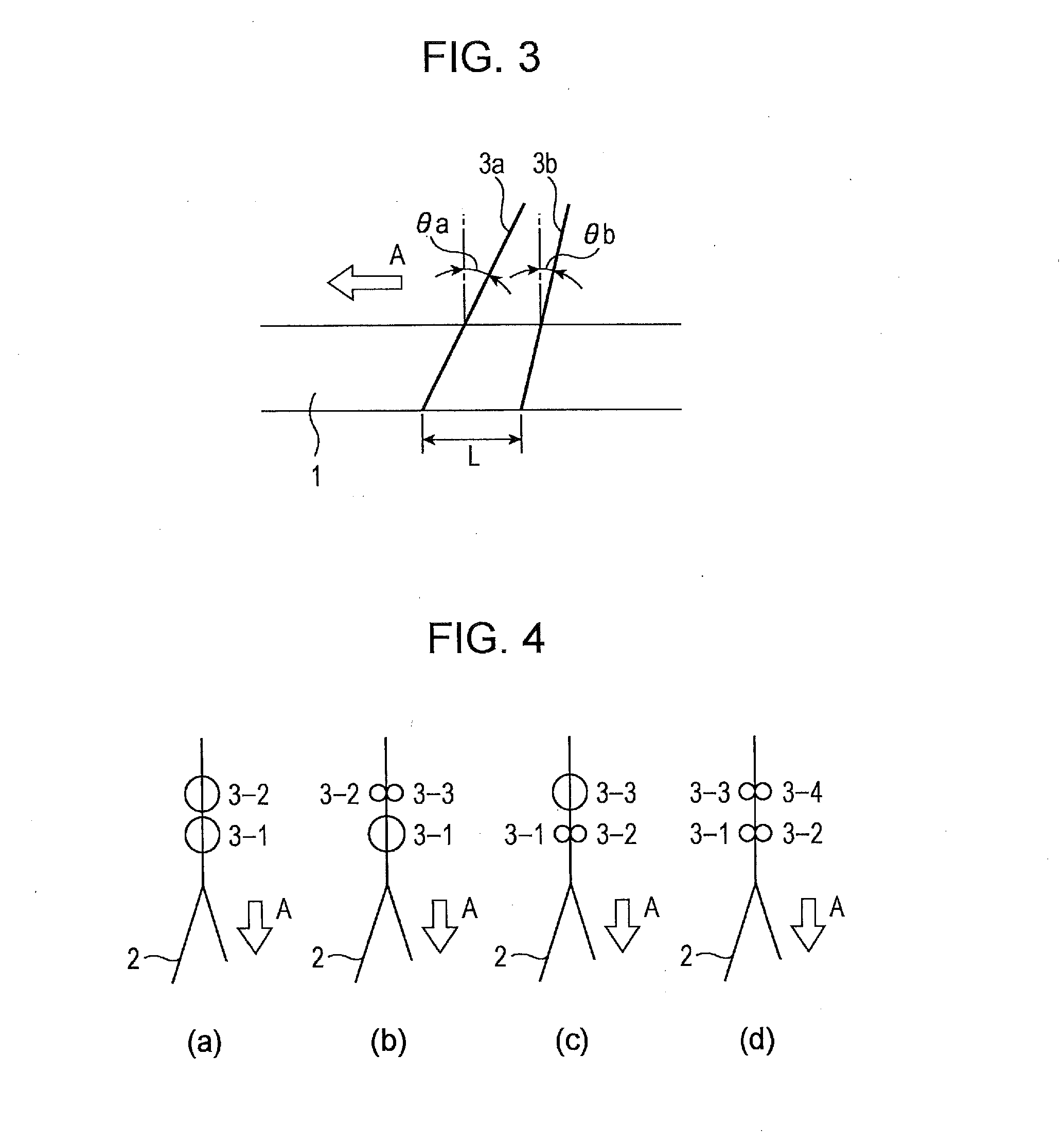
[0063]Laser welding was performed using two fiber laser oscillators with a maximum output of 10 kW with the settings being made as shown in Table 2. The distance t (mm) from the upper surface of each open pipe to the focus was fixed to ½T with respect to the strip thickness T. The laser beam incident angles θa and θb shown in Table 2 indicate the angles illustrated in FIG. 3. An incident angle having a negative value indicates that the laser beam is emitted while being inclined toward a direction opposite to the direction A in which welding proceeds.

[0064]Welded steel pipes Nos. 1 to 4 and 7 to 10 shown in Table 2 are examples obtained when the laser beams...


PUM

PropertyMeasurementUnit
diametersaaaaaaaaaa
incident anglesaaaaaaaaaa
speedaaaaaaaaaa

Abstract

A method of manufacturing a laser welded steel pipe by forming a steel strip into a cylindrical open pipe and performing laser welding on edges that includes: emitting two laser beams along the edges from an upper surface side of the open pipe, the two laser beams being transmitted through different optical fibers with in-focus spot diameters exceeding 0.3 mm; emitting leading and trailing laser beams each inclined toward a direction in which welding proceeds at an incident angle with respect to a direction perpendicular to an upper surface of the open pipe; setting the incident angle of the leading laser beam to be larger than the incident angle of the trailing laser beam; and setting a gap between a center point of the leading laser beam and a center point of the trailing laser beam on a back surface of the open pipe to 1 mm or larger.

Description

TECHNICAL FIELD[0001]The present invention relates to a method of manufacturing a steel pipe (or steel tube, hereinafter called a laser welded steel pipe) by welding longitudinal edges of an open pipe together using a laser beam, and particularly to a method of manufacturing a laser welded steel pipe appropriate for drilling and transporting oil or natural gas, such as oil country tubular goods or a line pipe.BACKGROUND ART[0002]Steel pipes used as oil country tubular goods or line pipes are broadly divided into welded steel pipes (for example, electric resistance welded steel pipes, UOE steel pipes, and other pipes) and seamless steel pipes. Among these steel pipes, electric resistance welded steel pipes are advantageous from an economical point of view because they can be manufactured at a low cost by using steel strips formed by hot rolling (so called hot rolled steel coils) as a starting material.[0003]However, a typical electric resistance welded steel pipe inevitably includes ...

Claims


Application Information

Patent Timeline
Patent Type & Authority Applications(United States)
IPC IPC(8): B23K26/28B21C37/08B23K26/00B23K26/064B23K26/067B23K26/21
CPCB21C37/08B23K26/285B23K26/0608B23K26/32B23K26/262B23K2103/04B23K2103/50B23K26/282B23K2101/06
Inventor YANO, KOJISUMI, HIROYUKIOI, KENJI
Owner JFE STEEL CORP
Learn More