Laser Interference Lithography Apparatus Using Fiber as Spatial Filter and Beam Expander

a lithography apparatus and fiber technology, applied in the field of laser interference lithography (lil) apparatus, can solve the problems of loss of contrast ratio or pattern shape, large depth of focus, and significant decrease of the influence of the environment on the exposur

Inactive Publication Date: 2014-05-01
NATIONAL TSING HUA UNIVERSITY
View PDF4 Cites 7 Cited by
  • Summary
  • Abstract
  • Description
  • Claims
  • Application Information

AI Technical Summary

Benefits of technology

[0011]An object of the invention is to provide a laser interference lithography apparatus using one or more fibers with the transmission property to serve as and replace a spatial filter and a beam expander, to provide a physically flexible beam transport system without additional optical elements, and to provide a pure, stable and coherent laser beam as an exposure light source to perform the LIL process.
[0013]According to the above-mentioned aspect of the invention, the fiber can be used to filter out the spatial noise, so that the pure and stable single mode laser beam without the spatial noise can be provided for LIL.

Problems solved by technology

Fourth, LIL has a large depth of focus, and can significantly decrease the influence of the environment on the exposure.
Under the nanometer scale, either the laser pointing drifting or the vibration causes the change of the period or position of the interference pattern, resulting in the loss in contrast ratio or pattern shape.
Although the real-time correction can be performed using the precise measurement and control, the burden of the relatively high costs and complexity of the apparatus and the technique are a substantial disadvantage.
In addition, all laser sources will produce spatial noise to varying degrees.
Imperfection in these devices, including lenses, mirrors, and contaminants on their surfaces can produce further spatial noise.
However, the position of the pin hole has to be properly adjusted because the poor effect is caused when the pin hole is too close to or away from the laser source, or drifts laterally, perpendicular to the beam direction.
Thus, a fringe-locking system is often required using a complicated optical mechanism, an optical detection device and a precise optical device in conjunction with the high-speed and real-time feedback system, and this establishing process is time consuming and adds substantially to the cost and complexity of construction and operation.

Method used


Image

  • Laser Interference Lithography Apparatus Using Fiber as Spatial Filter and Beam Expander
  • Laser Interference Lithography Apparatus Using Fiber as Spatial Filter and Beam Expander
  • Laser Interference Lithography Apparatus Using Fiber as Spatial Filter and Beam Expander

Examples


Embodiment Construction

[0022]The present invention will be apparent from the following detailed description, which proceeds with reference to the accompanying drawings, wherein the same references relate to the same elements.

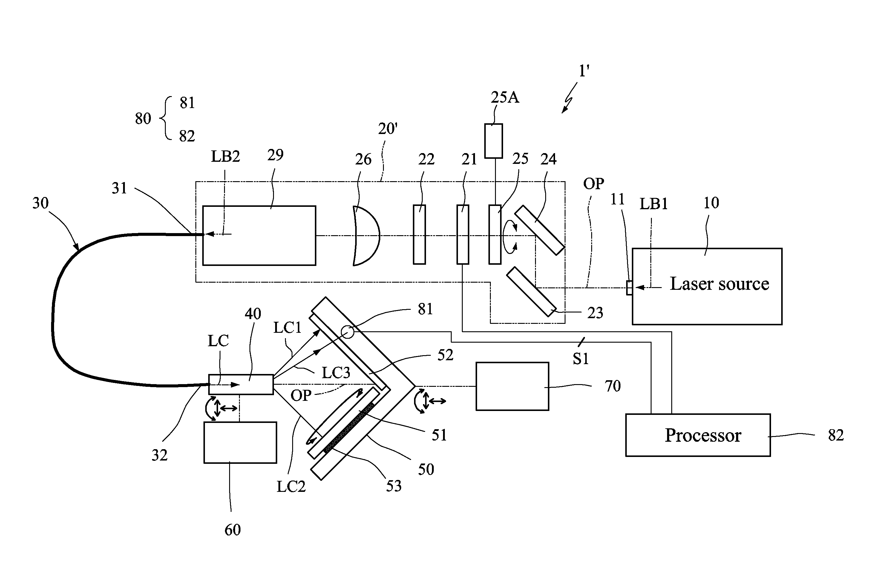
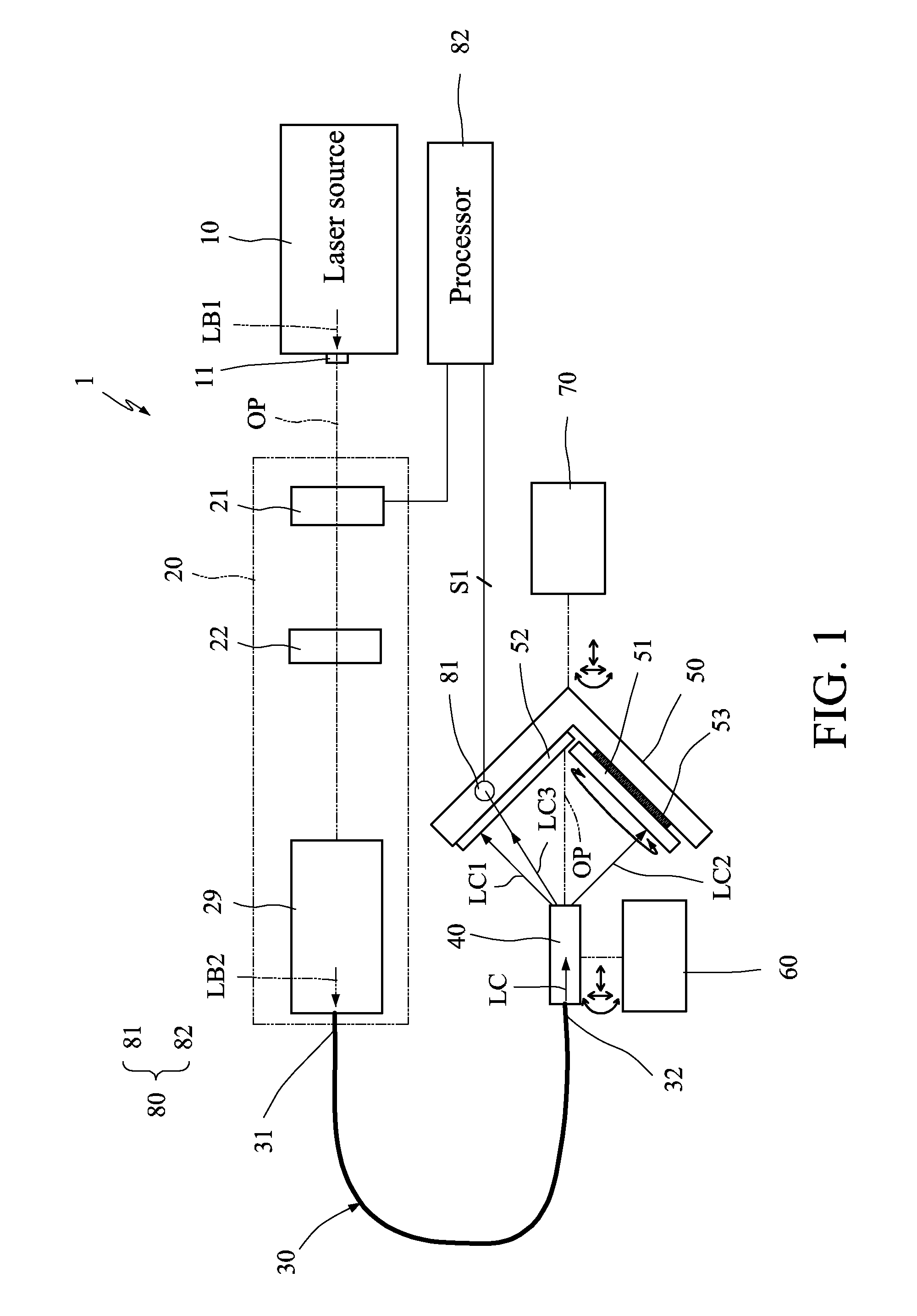
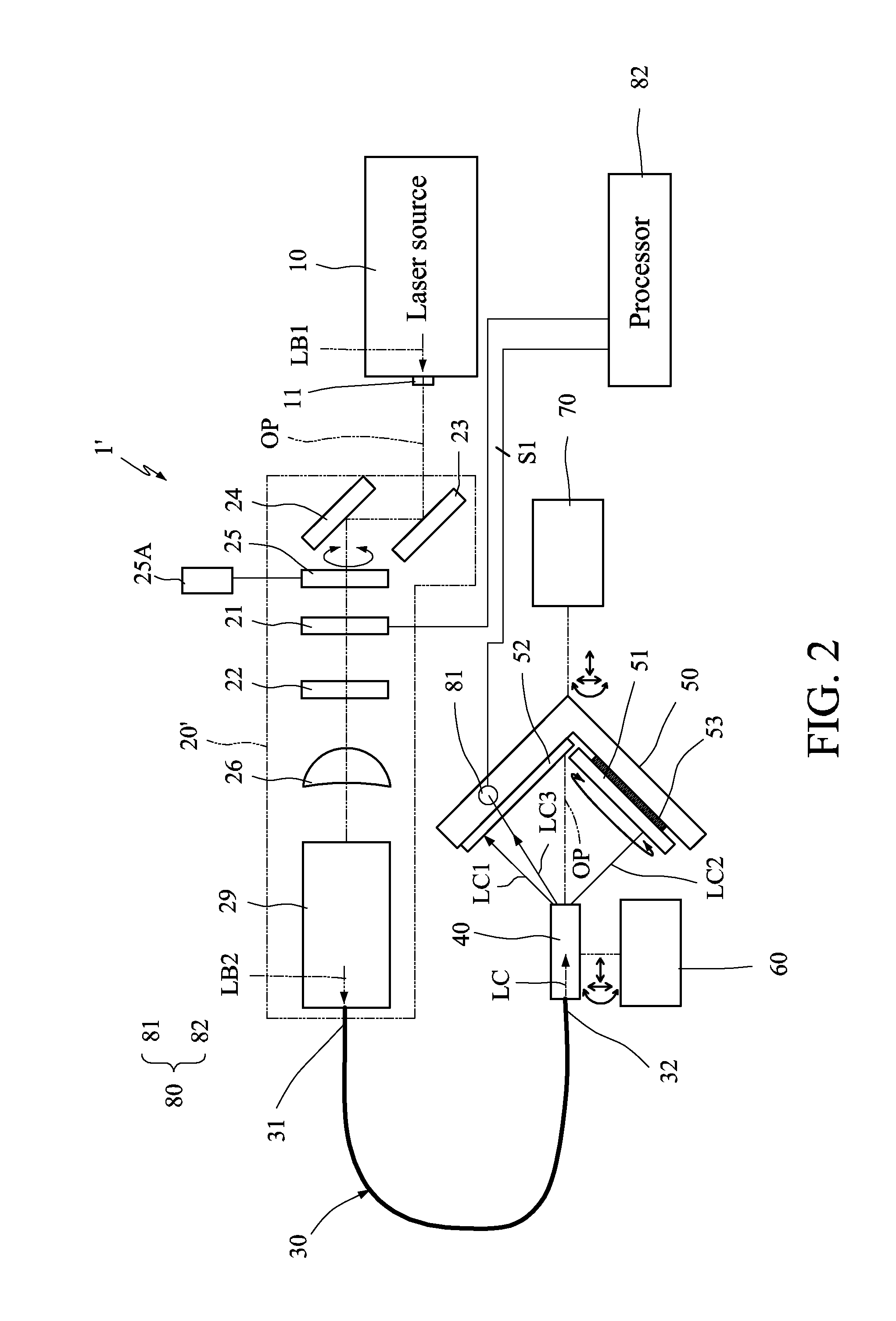
[0023]Referring to FIG. 1, a laser interference lithography (LIL) apparatus 1 of this embodiment includes a laser source 10, an optics assembly 20, a fiber assembly 30, a holder 40 and an exposure stage 50. It is to be noted that the relative position relationships between the elements in FIG. 1 are only for the illustrative purpose only but do not intend to restrict the scope of the invention.

[0024]The laser source 10 provides a first laser beam LB1. In one embodiment, a helium (He) cadmium (Cd) laser operating at 325 nm is selected to serve as the ultraviolet (UV) light source. Because the He Cd laser operates with the relatively low power plasma, the thermal Doppler broadening of the laser is naturally relatively low (about 1 GHz). For LIL of the sample with the dimension of severa...


PUM

PropertyMeasurementUnit
wavelengthaaaaaaaaaa
diameteraaaaaaaaaa
operating wavelengthaaaaaaaaaa

Abstract

In a laser interference lithography apparatus, a laser source provides a first laser beam, and an optics assembly is optically coupled to the laser source and receives and processes the first laser beam into one or multiple second laser beams. An exposure stage carries a to-be-exposed object. The fiber assembly receives and processes the second laser beam(s) into one or multiple single mode and stable coherent third laser beams without spatial noise. An interference pattern is generated on the to-be-exposed object using the third laser beam(s). The apparatus is configured without a pin hole spatial filter and a beam expander being disposed on an optical path from an output end of the laser source to the exposure stage.

Description

[0001]This application claims priority of No. 101139863 filed in Taiwan R.O.C. on Oct. 29, 2012 under 35 USC 119, the entire content of which is hereby incorporated by reference.BACKGROUND OF THE INVENTION[0002]1. Field of the Invention[0003]The invention relates to a laser interference lithography (LIL) apparatus with one or more optical fibers.[0004]2. Related Art[0005]LIL has been a low-cost and well-established method to produce nano-scale surface patterns that have high resolutions. LIL uses coherent light beams, which are split and reflected so that two or more than two beams overlap in the space, and interference fringes and periodic structures are formed on a photosensitive layer such as photoresist. LIL has the following advantages. First, LIL does not require a photomask or an imaging projection lens set with high numerical aperture (NA) value, wherein the mask and the lens set are used in the conventional projection photolithography technology. Second, a simple single tra...

Claims


Application Information

Patent Timeline
Patent Type & Authority Applications(United States)
IPC IPC(8): G03F7/20
CPCG03F7/70408
Inventor FU, CHIEN-CHUNGSUN, YI-LINMIKOLAS, DAVID GERARDLIN, PAO-TECHANG, EN-CHIANGHUANG, TZE-BIN
Owner NATIONAL TSING HUA UNIVERSITY
Why Eureka
Try Eureka