Eureka AIR delivers breakthrough ideas for toughest innovation challenges, trusted by R&D personnel around the world.

Fine-structure layered product, preparation method of the fine-structure layered product and manufacturing method of a fine-structure product

a technology of fine-structure layered products and manufacturing methods, which is applied in the direction of liquid/solution decomposition chemical coatings, instruments, applications, etc., can solve the problems of increasing drawing time, affecting the quality of the product, etc., and achieves excellent environmental resistance, weather resistance and long-term stability, and high productivity.

Inactive Publication Date: 2013-12-05
ASAHI KASEI KK
View PDF9 Cites 55 Cited by
  • Summary
  • Abstract
  • Description
  • Claims
  • Application Information

AI Technical Summary

Benefits of technology

The invention is about a way to make a layered product with a lot of tiny bumps and holes that are resistant to environmental factors like weather and can be made quickly and easily. The technical effects are that it allows for a large, high-quality layered product to be made with high efficiency.

Problems solved by technology

However, in photolithography techniques, there is a problem that it is difficult to perform processing on a pattern less than or equal to a wavelength of light used in exposure.
However, in the EB method, since a mask pattern is directly drawn using an electron beam, there is a problem that the drawing time increases as the drawing patterns increase, and that throughput up to pattern formation extremely decreases.
Further, due to high-precision control of a mask position in an exposure apparatus for photolithography, increases in the size of the electron beam lithography apparatus in an exposure apparatus for the EB method, and the like, there is also a problem that using these methods makes the apparatus cost high.
However, such a method requires a die enduring high-temperature pressurization conditions and the nanoimprint process including the heat cool process.
Therefore, a large facility is required, and such a problem occurs that the cycle time is long.
However, in this method, since the mold is pressed against the ceramic fine-particle slurry and baked, many asperities derived from fine particles are formed on the surface subjected to baking.
Therefore, in the method, it is difficult to form a fine concavo-convex structure accurately reflecting the fine concavo-convex structure of the mold.
Further, since it is necessary to use a rigid body such as a silicone mold as the mold, there is also the problem with uniform transfer characteristics to a larger area.
However, in this method, since it is necessary to use a large amount of fluorine-containing resin that is expensive to enhance release properties between the inorganic hardened product and the mold, there is a problem of being poor in economy.
Further, thermal transfer should be used in formation of the fine concavo-convex structure to the fluorine-containing polymer mold due to properties of the material, and large thermal shrinkage becomes a problem in transferring to a large area.
Furthermore, transfer to the inorganic hardened product is of a batch type, and the method is also inferior in production efficiency.

Method used


Image

  • Fine-structure layered product, preparation method of the fine-structure layered product and manufacturing method of a fine-structure product
  • Fine-structure layered product, preparation method of the fine-structure layered product and manufacturing method of a fine-structure product
  • Fine-structure layered product, preparation method of the fine-structure layered product and manufacturing method of a fine-structure product

Examples


embodiment 1

[0085]In Embodiment 1, as the inorganic layer 13, used is a hardened sol-gel material layer (hardened material layer of the sol-gel material) that is a hardened material of the sol-gel material. The sol-gel material is a compound group such that hydrolytic polycondensation proceeds by action of heat and catalyst and that the material is hardened. Examples thereof are metal alkoxide (metal alcoholate), metal chelate compounds, metal halide, silane halide, liquid glass, spin-on glass or reactants thereof, or these compounds or reactants with a catalyst to promote hardening contained. Corresponding to required physical properties, the compounds or reactants may be used alone, or in combination of a plurality of kinds. Further, siloxane materials including silicone, reaction inhibitor and the like may be contained in the sol-gel material. Furthermore, as the sol-gel material, it is possible to use not only an unhardened material but also a partially hardened material. Herein, the partia...

embodiment 2

[0113]Embodiment 2 will be described next. In Embodiment 2, as the inorganic layer 13, used is an inorganic material layer that is a layer in which an unhardened sol-gel material is further contained in the hardened material of the sol-gel material. By thus using the hardened material of the sol-gel material, control of the refractive index is made ease. Further, the sol-gel material is added to voids and the like existing in the hardened material of the sol-gel material to fill the voids, and it is thereby possible to obtain the effects such as improvements in the refractive index and improvements in physical strength. Furthermore, since the unhardened sol-gel material functions as an adhesive, it is possible to laminate the inorganic material layer to another substrate. As a method of containing a unhardened sol-gel material in the hardened material of the sol-gel material, there are a method of immersing the hardened material in a solution of the sol-gel material, another method ...

embodiment 3

[0117]Embodiment 3 will be described next. In Embodiment 3, as the inorganic layer 13, used is an inorganic fine-particle layer that is a layer containing a mixture of inorganic fine particles, binder polymer and sol-gel material. The inorganic fine-particle layer is a layer containing a mixture of inorganic fine particles, binder polymer and sol-gel material. By fixing inorganic fine particles with binder polymer, and adding the sol-gel material to voids thereof, since it is possible to fill voids of the inorganic fine-particle layer with the sol-gel material, it is possible to obtain the effects such as improvements in the refractive index and improvements in physical strength. Further, since the sol-gel material functions as an adhesive, it is possible to laminate the inorganic fine-particle layer to another substrate.

[0118]As the sol-gel material forming the inorganic fine-particle layer, it is possible to use the same material as the material forming the hardened sol-gel materi...


PUM

PropertyMeasurementUnit
distanceaaaaaaaaaa
heightaaaaaaaaaa
pressureaaaaaaaaaa

Abstract

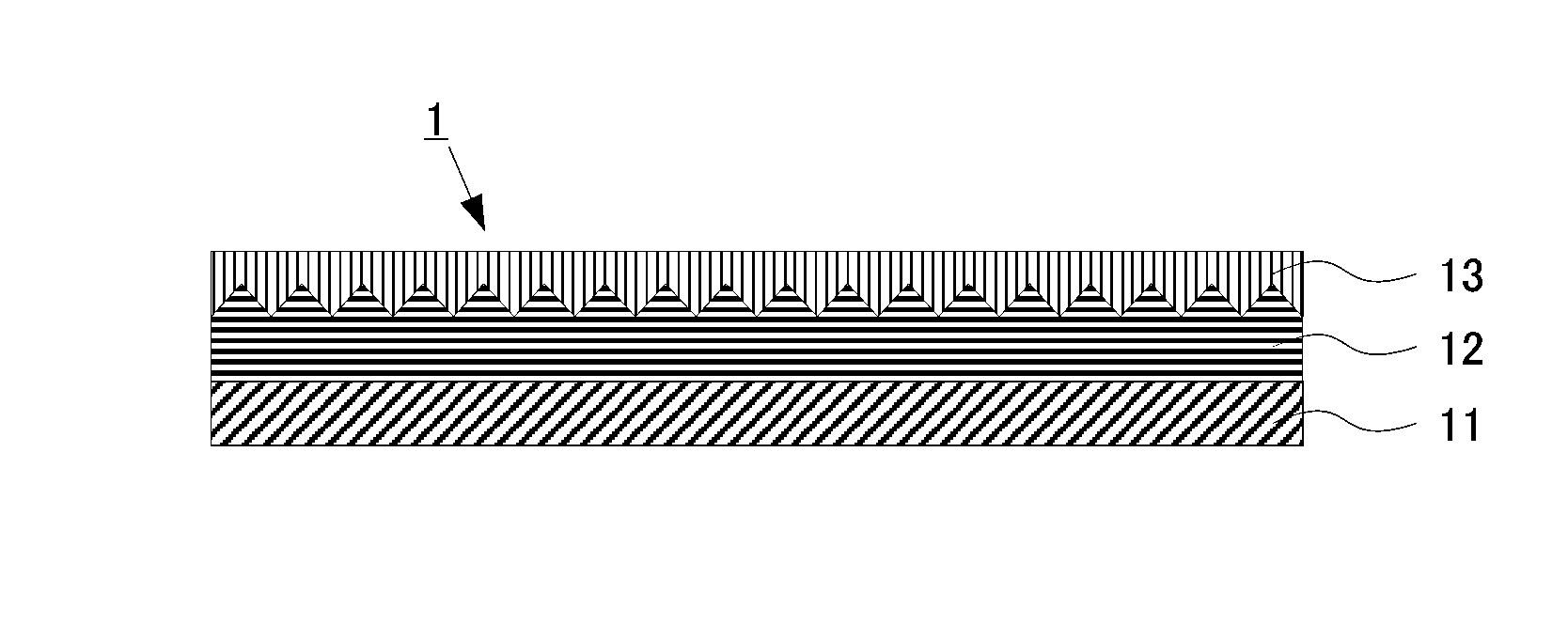
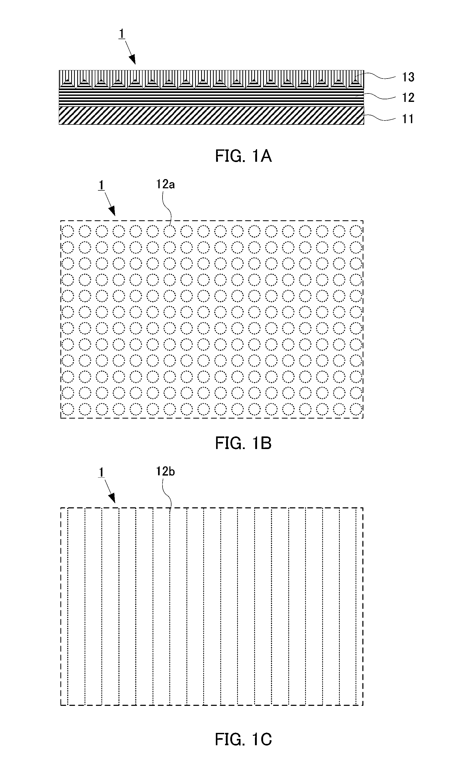
To provide a fine-structure layered product, and a preparation method of a fine-structure layered product using the fine-structure layered product for enabling a fine concavo-convex structure excellent in environmental resistance, weather resistance and long-term stability to be formed with a large area and high productivity, and provide a manufacturing method of a fine-structure product for enabling a large area to be made with high productivity, a fine-structure layered product of the invention is provided with a substrate, a resin layer that is formed on one main surface of the substrate and that has a fine concavo-convex structure on its surface, and an inorganic layer that is provided on the fine concavo-convex structure of the resin layer and that contains a sol-gel material having a fine concavo-convex structure in a shape associated with the fine concavo-convex structure of the resin layer, where a fluorine element concentration (Es) in a region on the inorganic layer side of the resin layer is higher than an average fluorine concentration (Eb) in the resin layer.

Description

TECHNICAL FIELD[0001]The present invention relates to a fine-structure layered product used in formation of a fine concavo-convex structure, and a preparation method of a fine-structure layered product using the fine-structure layered product.BACKGROUND ART[0002]Conventionally, as fine pattern processing techniques in LSI manufacturing, photolithography techniques have been used frequently. However, in photolithography techniques, there is a problem that it is difficult to perform processing on a pattern less than or equal to a wavelength of light used in exposure. As other fine pattern processing techniques, there are mask pattern lithography techniques (EB method) with electron beam lithography apparatuses. However, in the EB method, since a mask pattern is directly drawn using an electron beam, there is a problem that the drawing time increases as the drawing patterns increase, and that throughput up to pattern formation extremely decreases. Further, due to high-precision control...

Claims


Application Information

Patent Timeline
Patent Type & Authority Applications(United States)
IPC IPC(8): G02B1/10F21V3/00
CPCG02B1/105H01L31/02366C23C18/1216C23C18/122C23C18/1233C23C18/1245Y10T428/24537B29C59/02B32B3/30B32B27/302H01L21/0273G02B1/14Y02E10/50G02B1/10
Inventor KOIKE, JUNITO, RYUICHIYAMAGUCHI, FUJITO
Owner ASAHI KASEI KK
Why Eureka
Eureka Blog
Learn More