
Microelectronic substrate inspection equipment using helium ion microscopy

a technology of helium ion microscopy and microelectronic substrates, applied in semiconductor/solid-state device testing/measurement, instruments, nuclear engineering, etc., can solve the problems of damage and contamination of samples, optical inspection equipment may have limitations in its detection capability, and the numerical aperture may be increased by 1 or more or the wavelength of a light sour

Active Publication Date: 2013-07-11
SAMSUNG ELECTRONICS CO LTD
View PDF3 Cites 9 Cited by
  • Summary
  • Abstract
  • Description
  • Claims
  • Application Information

AI Technical Summary

Benefits of technology

The patent describes a new type of inspection equipment that can inspect patterns on microelectronic substrates using a helium ion microscope (HIM). The equipment is able to get 3D stereoscopic information about these patterns. This technology allows for more precise inspection of microelectronic patterns and ensures better quality control during the manufacturing process.

Problems solved by technology

However, optical inspection equipment may have limitations in its detection capability due to optical diffraction.
However, there may be limitations in increasing the numerical aperture by 1 or more or reducing the wavelength of a light source.
However, an electron beam used by the electron beam inspection equipment can cause electric charges to be charged on a sample or cause damage and contamination of the sample.
In addition, electron beam inspection equipment may require a high-vacuum or ultra-high vacuum operating environment and may only obtain 2D planar information, instead of stereoscopic information, due to its small depth of focus (DOF).

Method used


Image

  • Microelectronic substrate inspection equipment using helium ion microscopy
  • Microelectronic substrate inspection equipment using helium ion microscopy
  • Microelectronic substrate inspection equipment using helium ion microscopy

Examples


Embodiment Construction

[0023]The present inventive concepts will now be described more fully hereinafter with reference to the accompanying drawings, in which preferred embodiments of the invention are shown. This invention may, however, be embodied in different forms and should not be construed as limited to the embodiments set forth herein. Rather, these embodiments are provided so that this disclosure will be thorough and complete, and will fully convey the scope of the invention to those skilled in the art. The same reference numbers indicate the same components throughout the specification. In the attached figures, the thickness of layers and regions is exaggerated for clarity.

[0024]It will be understood that when an element or layer is referred to as being “connected to,” or “coupled to” another element or layer, it can be directly connected to or coupled to another element or layer or intervening elements or layers may be present. In contrast, when an element is referred to as being “directly conne...


PUM


Abstract

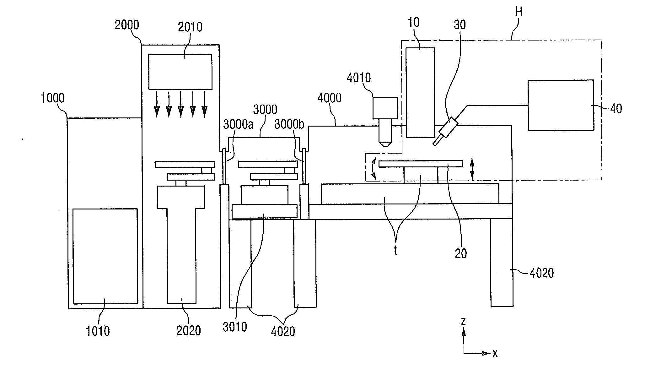
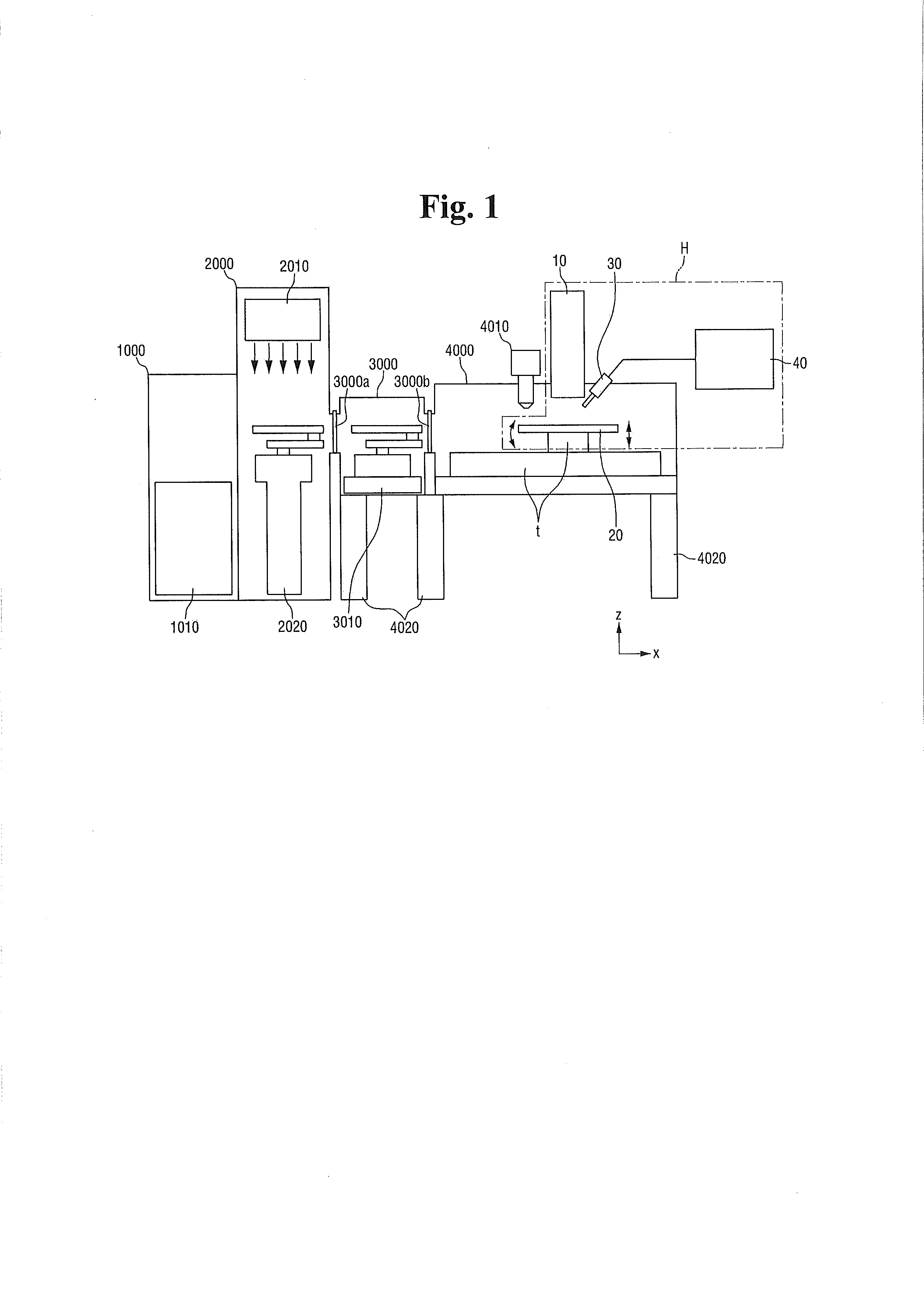
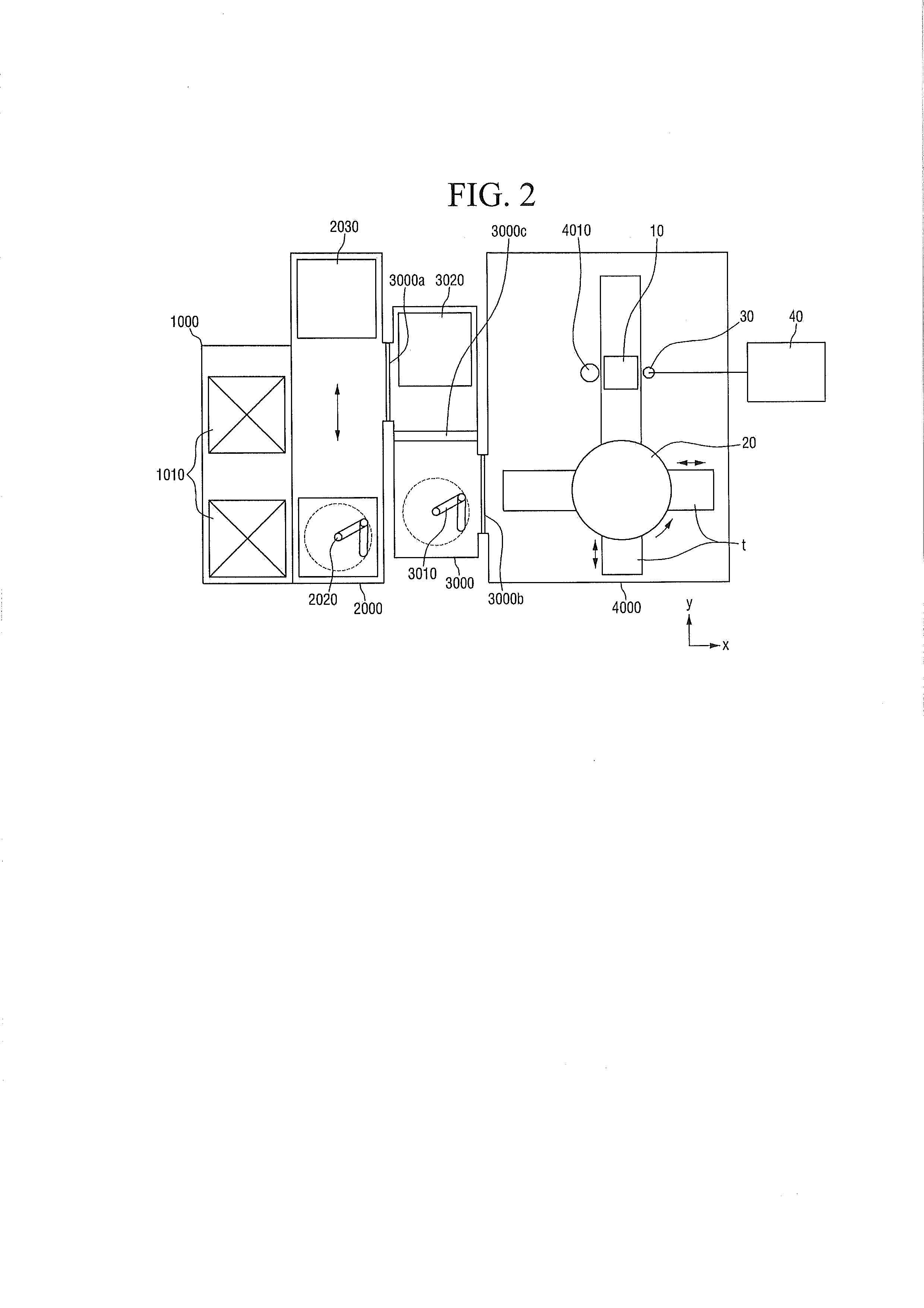
Microelectronic substrate inspection equipment includes a gas container which contains helium gas, a helium ion generator which is disposed in the gas container and converts the helium gas into helium ions and a wafer stage which is disposed under the gas container and on which a substrate to be inspected is placed. The equipment further includes a secondary electron detector which is disposed above the wafer stage and detects electrons generated from the substrate, a compressor which receives first gaseous nitrogen from a continuous nitrogen supply device and compresses the received first gaseous nitrogen into liquid nitrogen, a liquid nitrogen dewar which is connected to the compressor and stores the liquid nitrogen, and a cooling device that is coupled to the helium ion generator. The cooling device is disposed on the gas container, and cools the helium ion generator by vaporizing the liquid nitrogen. Related methods are also disclosed.

Description

CROSS REFERENCE TO RELATED APPLICATION[0001]This application claims priority from Korean Patent Application No. 10-2012-0003497 filed on Jan. 11, 2012 in the Korean Intellectual Property Office, the disclosure of which is incorporated herein by reference in its entirety.BACKGROUND[0002]1. Field of the Invention[0003]The present inventive concepts relate to microelectronic substrate inspection equipment and microelectronic substrate inspection methods using the same.[0004]2. Description of the Related Art[0005]With the increasing precision of semiconductor processes, pattern sizes are becoming smaller, and step heights are becoming greater. To inspect a pattern to see if the pattern has been formed according to design values, optical inspection equipment is generally used. However, optical inspection equipment may have limitations in its detection capability due to optical diffraction. Since the process of detecting a fine pattern with a great step height requires an increasingly hig...

Claims


Application Information

Patent Timeline
IPC IPC(8): H01J37/20
CPCH01J37/08H01J2237/002H01J37/265H01J2237/0807H01J2237/006H01L22/00
Inventor KIM, MIN-KOOKKO, WOO-SEOKYANG, YU-SINLEE, SANG-KILCHOI, CHANG-HOON
Owner SAMSUNG ELECTRONICS CO LTD
Learn More