
Anesthetic Inhalation Aid Device and Attachment Used for the Same

a technology of inhalation aid and inhalation chamber, which is applied in the direction of combustion types, applications, lighting and heating apparatus, etc., can solve the problems of brain damage, irreversible brain damage, and metabolic and bloodstream imbalance, and achieve the effect of convenient handling

Active Publication Date: 2013-05-16
ISHIKITA NAOYUKI
View PDF5 Cites 18 Cited by
  • Summary
  • Abstract
  • Description
  • Claims
  • Application Information

AI Technical Summary

Benefits of technology

The anesthetic inhalation aid device is designed to be easy to use and quickly administer anesthetic to patients. Its technical effect is to provide a convenient and effective way to provide anesthesia to patients.

Problems solved by technology

In particular, if status epilepticus in which firing throughout the cerebral cortex lasts for several tens of minutes or longer from the start of the seizure occurs, an imbalance between metabolic and bloodstream is caused, which may lead to irreversible brain damage.
Even if hypoxemia, hypoglycemia, or local circulatory disorder is not caused, the excessive neuroelectronic activity itself causes brain damage.
Status epilepticus is therefore known to cause severe mental or neurological aftereffects due to this irreversible brain damage.
Within a certain period of time after status epilepticus occurs, brain damage is less likely to be caused owing to a compensatory action; however, if treatment takes time, compensation becomes impossible, and severe brain damage is therefore likely to be developed.
It is, however, difficult to safely give the injection to a patient being in a convulsive state.
In addition, if a medicine is excessively administered, it is difficult to remove the medicine from the body, which causes the risk of unstable cardiorespiratory functions.
Although attempts at easier methods have been also made, such as administration of a suppository and enema administration of an intravenous medicine, these methods have unsatisfactory immediate effects and are therefore unlikely to terminate convulsions at an early stage.

Method used


Image

  • Anesthetic Inhalation Aid Device and Attachment Used for the Same
  • Anesthetic Inhalation Aid Device and Attachment Used for the Same
  • Anesthetic Inhalation Aid Device and Attachment Used for the Same

Examples


first embodiment

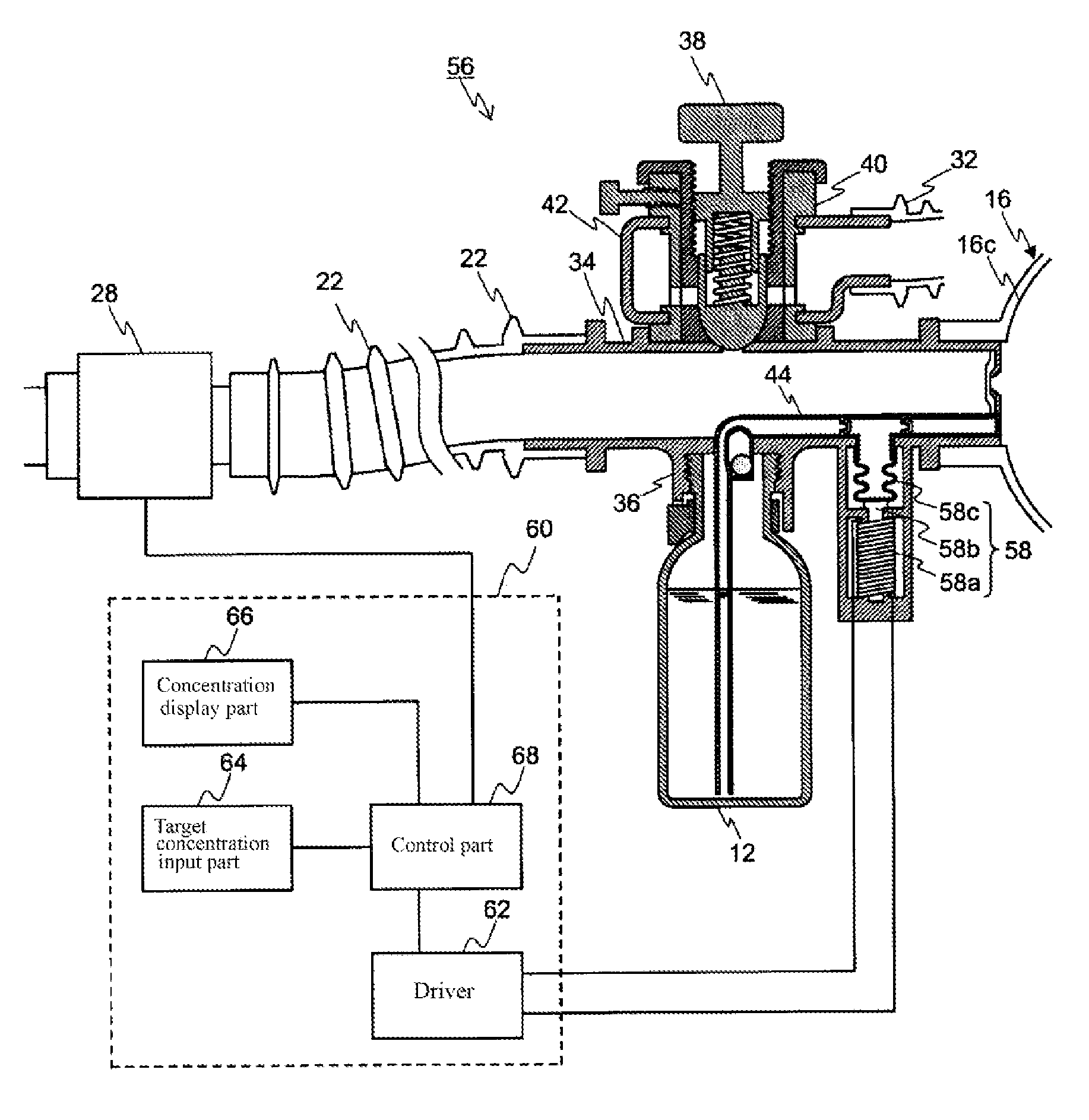
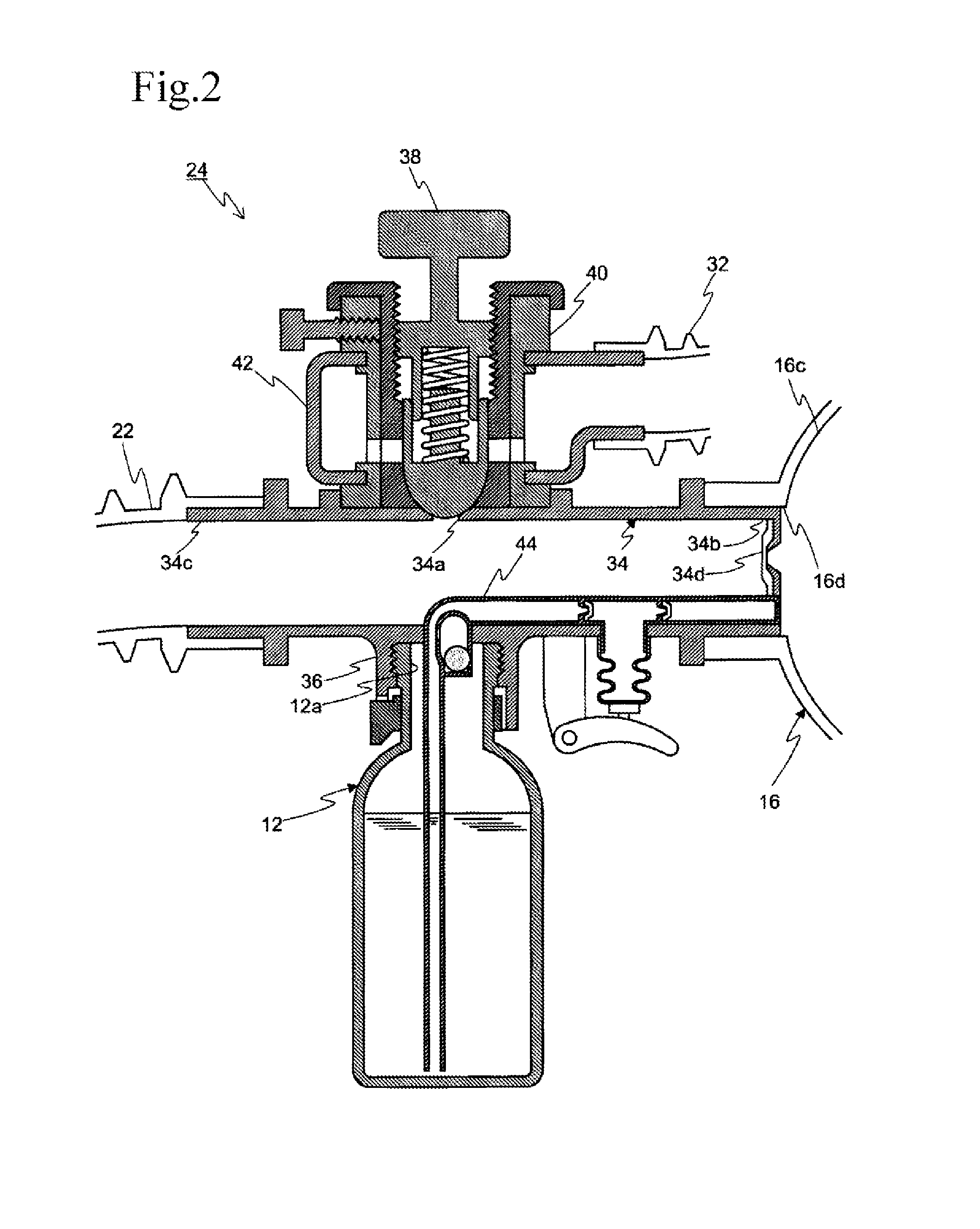
[0034]FIG. 1 illustrates an example of an anesthetic inhalation aid device according to a An anesthetic inhalation aid device 10 enables inhalation administration of an anesthetic to a patient 14, the anesthetic being supplied from an anesthetic bottle 12 being a reservoir of the anesthetic. The anesthetic inhalation aid device 10 includes an elastic bag 16, an inhalation mask 18, an artificial nose unit 20, an extension tube 22, an anesthesia attachment 24, anesthetic removal equipment 26, an anesthetic gas concentration detector 28, a display 30, and an exhaust tube 32.

[0035]The elastic bag 16 functions as a mixer and has an anesthetic inlet 16a for introducing an anesthetic held by the anesthetic bottle 12 to the interior through the anesthesia attachment 24 which will be described in detail later, an air inlet 16b with a backflow prevention function for unidirectionally introducing air to the interior, a mixing chamber 16c for mixing the introduced anesthetic with the introduce...

third embodiment

[0094]The operation of the anesthetic inhalation aid device 10 of the third embodiment will now be described.

[0095]The expired air of the patient 14 is introduced from the extension tube 22 into the first tube 78 and second tube 80 of the anesthesia attachment 70.

[0096]The expired air introduced into the first tube 78 applies pressure to the anesthetic check valve 86 to open the same and then is introduced from the expired air inlet 74a into the anesthetic bottle 12 with the guidance of the expired air introduction tube 74. Secretions contained in the expired air of the patient 14 are collected by the artificial nose filter inserted into the artificial nose unit 20 and do not therefore substantially enter the anesthetic bottle 12.

[0097]The expired air introduced into the anesthetic bottle 12 applies pressure to an anesthetic held by the anesthetic bottle 12. The pressurized anesthetic is pumped out of the interior of the anesthetic bottle 12 to the nozzle 54 through an end of the an...

fourth embodiment

[0108]In the anesthetic inhalation aid device 88 of the fourth embodiment, at least the Vapo-Ject 92 or 98 is provided separately from the hollow structure 90, and the Vapo-Ject 92 or 98 is connected to the hollow structure 90 to form the anesthesia attachment 94, which can simplify mold design and reduce production costs as compared with the anesthesia attachment 24 or the like into which the anesthetic extraction unit 44 is integrally incorporated.

[0109]In addition, the anesthetic inhalation aid device 88 eliminates direct injection into the body and involves use of the Vapo-Ject 92 or 98 for injection of an anesthetic into the elastic bag 16 to administer vaporized anesthetic gas to the body through respiration; in this regard, the anesthetic inhalation aid device 88 is a unique medical device which does not meet the definition of the traditional inhalation anesthesia devices. Such a Vapo-Ject 92 or 98 is less likely to cause excess administration as compared with any other admin...


PUM


Abstract

An inhalation mask, an artificial nose unit, an anesthetic gas concentration detector, an extension tube, an anesthesia attachment, and an elastic bag are in communicative connection in sequence. The elastic bag has a mixing chamber formed therein and has an anesthetic inlet, an air inlet, and an outlet port each formed at the boundary to the exterior. The anesthesia attachment includes a hollow structure and an evaporation injector syringe. The outlet port of the elastic bag is in communicative connection with the hollow structure through its opening, and the evaporation injector syringe tightly mates with the interior of another opening. The anesthetic introduced into the mixing chamber is vaporized and then mixed with air introduced from the air inlet into mixed gas. The mixed gas is supplied from the outlet port to the inhalation mask by compressing the elastic bag or other procedures.

Description

TECHNICAL FIELD[0001]The present invention relates to an anesthetic inhalation aid device for administrating an anesthetic to a patient by inhalation, in particular, relates to an anesthetic inhalation aid device which can be easily handled and enables prompt inhalation administration of an anesthetic to a patient and an attachment used therefor.BACKGROUND ART[0002]A convulsive seizure induced by recurrent excessive firing of brain neurons is known to be attributed to various causes including not only central nervous system diseases, such as epilepsy and stroke, but also infections, such as encephalitis and meningitis, head injuries, acute alcoholism, and acute drug intoxication. In particular, if status epilepticus in which firing throughout the cerebral cortex lasts for several tens of minutes or longer from the start of the seizure occurs, an imbalance between metabolic and bloodstream is caused, which may lead to irreversible brain damage. Even if hypoxemia, hypoglycemia, or loc...

Claims


Application Information

Patent Timeline
IPC IPC(8): A61M16/10A61M11/02
CPCA61M16/01A61M16/209A61M11/02A61M16/104A61M11/06A61M16/0078A61M16/0816A61M16/1045A61M16/208A61M2016/1035A61M2205/071A61M2205/075A61M2205/3653A61M2205/502A61M2205/505A61M2205/6045A61M2205/6081A61M2205/8206A61M2230/04A61M2230/205A61M2230/30A61M2230/437A61M11/006A61M11/007A61M11/042A61M15/002A61M16/0093A61M16/18A61M16/0084
Inventor ISHIKITA, NAOYUKI
Owner ISHIKITA NAOYUKI
Learn More