
Laser apparatus and method of controlling the laser apparatus

a laser apparatus and laser technology, applied in the direction of ultrasonic/sonic/infrasonic diagnostics, instruments, applications, etc., can solve the problems of long time to stabilize the output, long consumption of lamps, and loss of convenience, so as to reduce the consumption of flash lamps and satisfy laser stability.

Inactive Publication Date: 2013-03-21
CANON KK
View PDF3 Cites 15 Cited by
  • Summary
  • Abstract
  • Description
  • Claims
  • Application Information

AI Technical Summary

Benefits of technology

The patent text describes a problem in laser technology where the flash lamp used to initiate the laser is consumed quickly when the laser is blocked, causing additional costs and delays in stabilizing the output. The present invention provides a solution that reduces both the consumption of the flash lamp and the time required for the laser to reach a stable output, resulting in improved efficiency and convenience.

Problems solved by technology

However, it takes a long time for a laser medium to reach a thermal equilibrium state when irradiation is restarted, so that it takes a long time to stabilize the output, and thus the convenience is lost.
Further, the light emission of the flash light when not in use corresponding to the warm-up time leads to the lamp consumption.
Meanwhile, when the output stability at the time when the laser light is irradiated is emphasized and the laser oscillation output at the time when the laser light is blocked is maintained similar to that at the time when the laser light is irradiated, the lamp consumption occurs due to unnecessary irradiation of the flash lamp.
Although PTL 2 discloses a method of performing laser output measurement and controlling the lamp current in view of indicating the exchange of the flash lamp based on the lamp consumption, this method is not a control method in view of extending the life of the flash lamp.
In the conventional examples, the output stability at the time of irradiation and the reduction of the lamp consumption at the time of light shielding cannot be satisfied simultaneously.
The simultaneous realization of the output stability and the reduction of the lamp consumption become significant problems in a laser apparatus for medical application, particularly a laser apparatus for diagnostic purposes, rather than industrial application such as processing and annealing conventionally often used as the application of a high-output lamp excitation solid laser.
Moreover, since the measurement conditions are often changed according to a condition of a subject, the use state is less likely to be standardized compared with the industrial application.
Consequently, the time when the laser apparatus is not used may be longer than the time when the laser apparatus is used, and thus it is very inefficient in terms of utilizing the flash lamp.

Method used


Image

  • Laser apparatus and method of controlling the laser apparatus
  • Laser apparatus and method of controlling the laser apparatus
  • Laser apparatus and method of controlling the laser apparatus

Examples


example 1

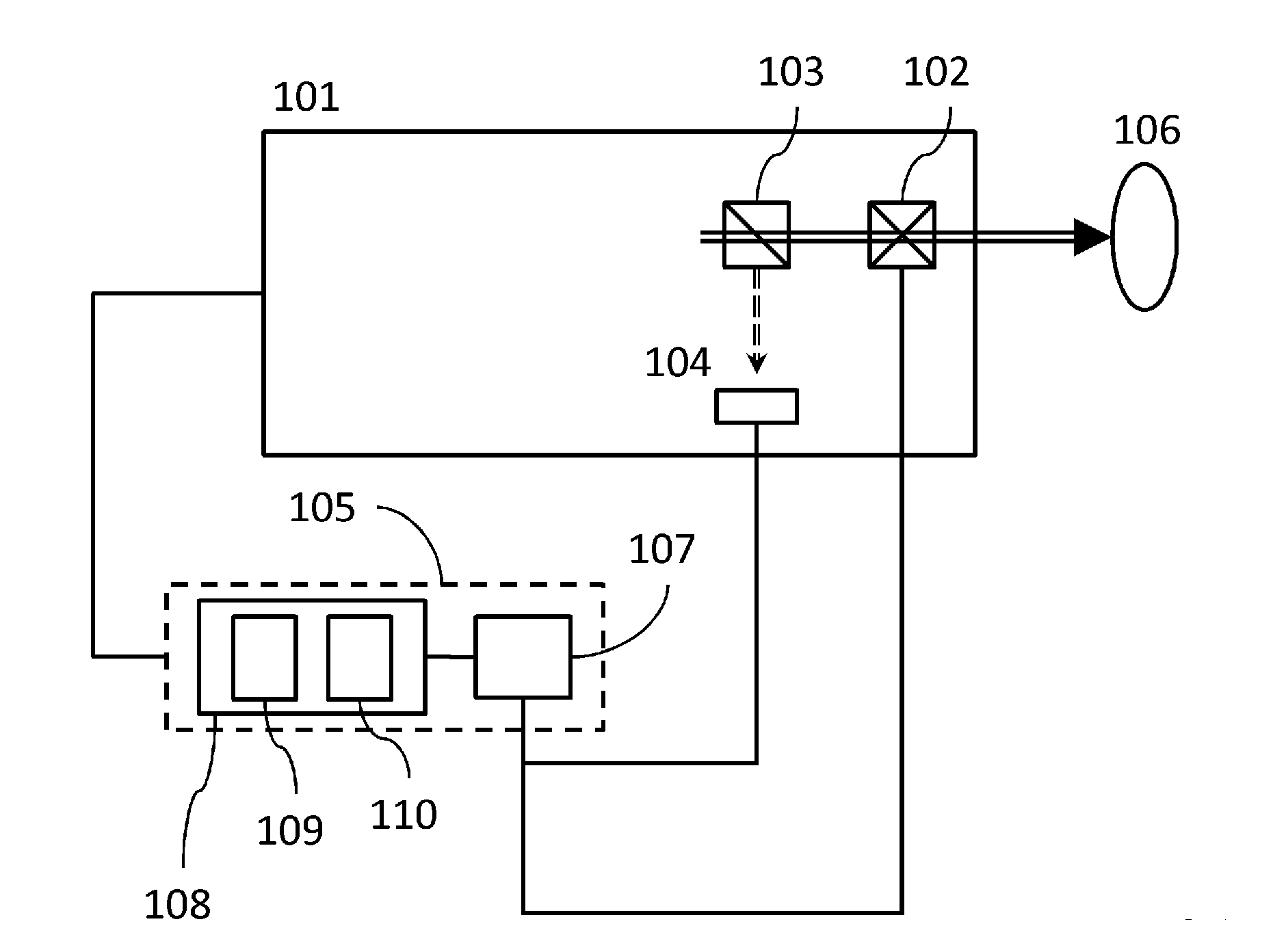
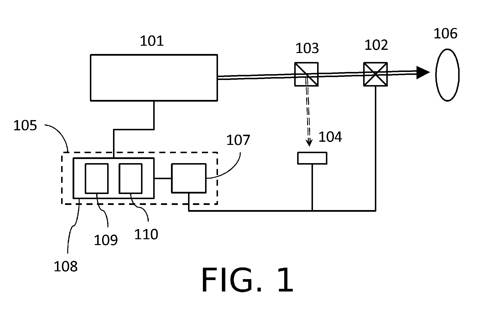
[0070]Hereinafter, an example of the method of controlling the laser apparatus used in a photoacoustic measurement apparatus for medical diagnosis is shown. The laser apparatus configured in FIG. 1 is used. This laser apparatus is constituted of the laser head portion 101, the light-shielding device 102 blocking a laser light, the beam splitter 103, the photodetector 104, and the control system 105 controlling the laser apparatus.

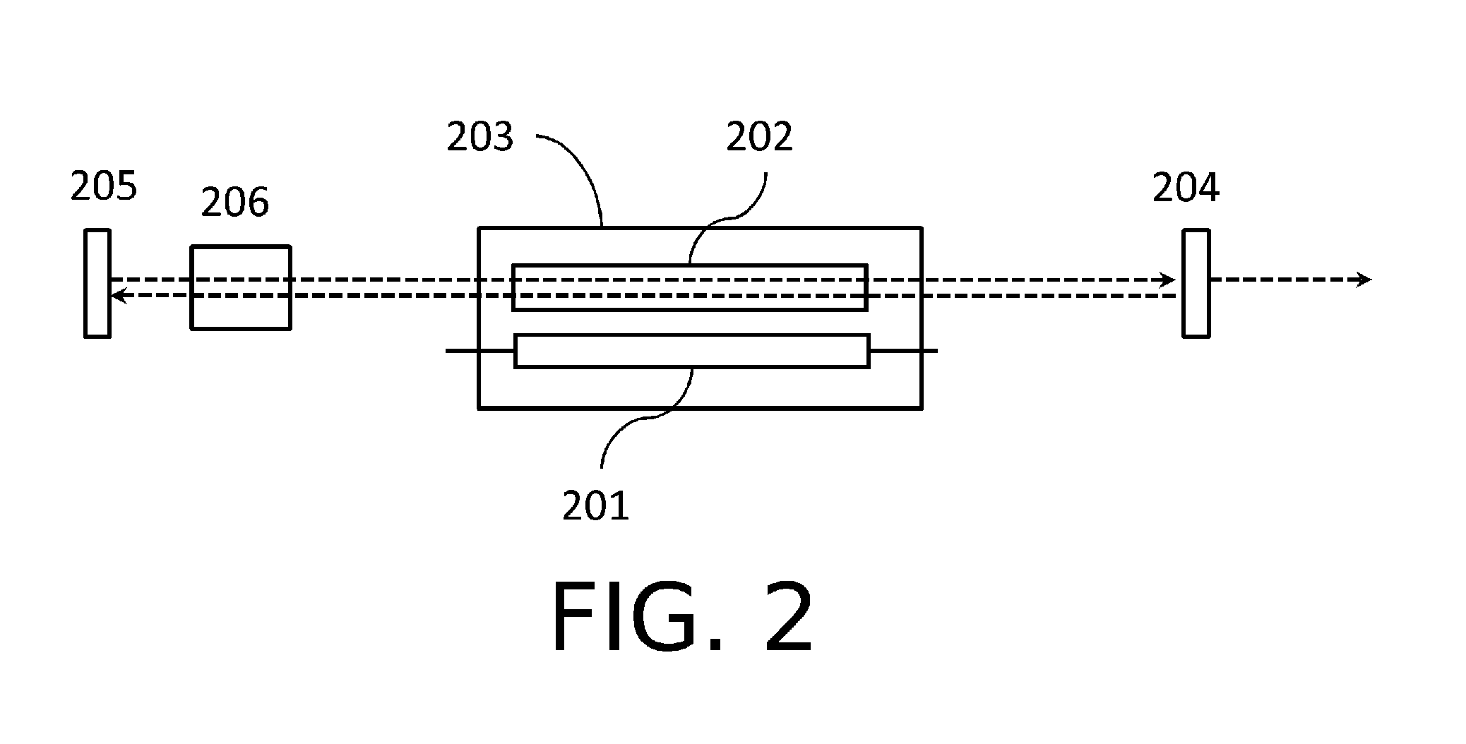
[0071]The laser head portion 101 is constituted of an Nd:YAG laser and a titanium-sapphire (Ti:sa) laser using second harmonics of the Nd:YAG laser as an excitation source. A breast phantom being a pseudo living body is used as the irradiated object 106. As the stable irradiation condition in the irradiation state 601, the lamp repetition frequency is 20 Hz, and the lamp current value that obtains the energy output of 100 mJ / pulse at a wavelength of 800 nm is used. In order to obtain a large pulse energy as an emission energy, a flash lamp is used as an exc...

example 2

[0084]Hereinafter, an example of the method of controlling the laser apparatus used in a photoacoustic measurement apparatus for medical diagnosis is shown. The laser apparatus configured in FIG. 1 is used. This laser apparatus is constituted of the laser head portion 101, the light-shielding device 102 blocking a laser light, the beam splitter 103, the photodetector 104, and the control system 105 controlling the laser apparatus.

[0085]An alexandrite laser is used in the laser head portion 101. A breast phantom being a pseudo living body is used as the irradiated object 106. As the stable irradiation condition in the irradiation state 601, the lamp repetition frequency is 20 Hz, and the lamp current value for obtaining the energy output of 100 mJ / pulse at a wavelength of 750 nm is 100 A. In order to obtain a large pulse energy as an emission energy, a flash lamp is used as an excitation source of the alexandrite laser. Each pulse light intensity is measured using a pyroelectric sens...


PUM

PropertyMeasurementUnit
Timeaaaaaaaaaa
Currentaaaaaaaaaa
Frequencyaaaaaaaaaa

Abstract

Disclosed is a method of controlling a laser apparatus, which has a laser light irradiation unit, an excitation unit including a flash lamp, a laser light shielding unit, and a control unit configured to control light shielding by the light shielding unit and release of the light shielding and control setting conditions of the flash lamp. The control unit performs a process of blocking the laser light by the light shielding unit when irradiation of the laser light is stopped, then performs a process of controlling the setting condition so that consumption of the flash lamp is reduced, performs, when the irradiation is restarted, a process of controlling the setting conditions so that the laser light is stably irradiated, and then performs a process of releasing the light shielding.

Description

BACKGROUND OF THE INVENTION[0001]1. Field of the Invention[0002]The present invention relates to a laser apparatus and a method of controlling the laser apparatus.[0003]2. Description of the Related Art[0004]Realization of a high output of a laser instrument has been progressed. Particularly, a solid laser typified by a Nd:YAG laser and so on using a laser medium obtained by adding neodymium (Nd) to Y3Al5O12 crystal as a base material is suitable for high energy application. Although a noble-gas flashlamp and a semiconductor laser (LD) are used as an excitation source of a solid laser, the noble-gas flash lamp has the advantage that it is inexpensive and energy output per pulse can be increased. Thus, the noble-gas flash lamp is widely used for industrial application such as a laser light machine and a laser annealing apparatus.[0005]Recently, the development of a photoacoustic measurement apparatus for medical use using a laser light has been progressed (NPL 1). In this apparatus, ...

Claims


Application Information

Patent Timeline
IPC IPC(8): H01S3/091A61B8/00B23K26/00B23K26/066G01N29/00G01N29/06H01S3/092H01S3/131
CPCH01S3/091H01S3/092H01S3/1312H01S3/005B23K26/426A61B5/0095A61B5/4312G01N29/2418B23K26/0643H01S3/1306B23K26/705
Inventor ICHIHARA, SHIGERU
Owner CANON KK
Learn More