
Coated and cured proppants

a technology of proppants and coatings, applied in the direction of coatings, pretreatment surfaces, borehole/well accessories, etc., to achieve the effects of low dust or fines generation, good crush resistance and fracture conductivity, and high production ra

Active Publication Date: 2013-03-14
PREFERRED TECH
View PDF3 Cites 80 Cited by
  • Summary
  • Abstract
  • Description
  • Claims
  • Application Information

AI Technical Summary

Benefits of technology

The invention is a coated proppant that has good crush resistance, resistance to dusting, and limited leaching of chemicals. The coating process results in a coated proppant that acts like it has a hybrid coating, with the ability to form particle-particle bonds at downhole conditions while also being resistant to high temperatures and having a low production cost. The coating process has a high production rate, low emission level, and does not lose bonding capability if exposed to elevated temperatures during handling or storage.

Problems solved by technology

A proppant that is flushed from the well is said to have a high “flow back.” Flow back is undesirable.
In addition to closure of the cracks, the flushed proppants are abrasive and can damage or clog the tubular goods used to complete the well, valves and pipelines in downstream processing facilities.
With some coatings, the synthetic coating is not completely cured when the proppant is introduced into the well.
Such partially cured coating can also exhibit a number of performance issues ranging from:A lack of storage stability if stored in a hot environment.
This type situation could result in a completion of the curing process while in storage making the coated proppant incapable of bonding when placed in the fracture.Leaching chemicals out of the partially cured coating that could interfere with the viscosity profile of the fluid used to carry the proppant into the fracture or the chemical breaker system that is relied on to reduce the frac fluid viscosity after completion of the fracturing treatment.Erosion of the partially cured coating when the coated proppant is handled pneumatically in order to place in the field storage bins at the well site.Premature curing in the fracture due to extended exposure to the elevated temperatures found downhole but before the cracks heal and begin to force the proppant grains into contact with each other.
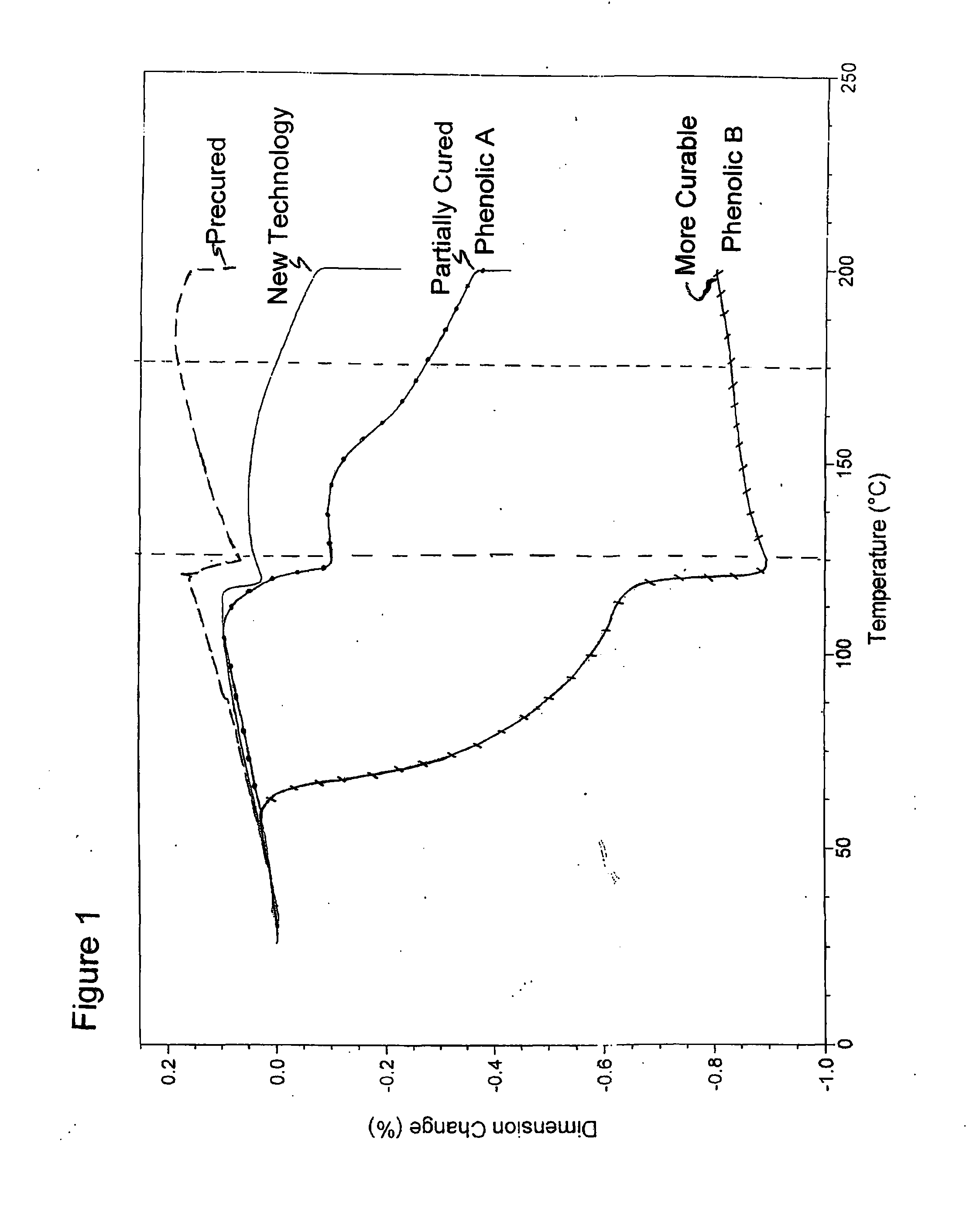
The main limitation of a pre-cured coating is that it cannot create significant particle to particle bonding when placed in the fracture and temperature and closure pressure are applied.
This means that a pre-cured coated particle can do little to prevent proppant flowback after the well is opened up to start the clean-up process or to produce the well.
Previously described polyurethanes have not, however, achieved widespread adoption due to their performance in the hot, wet, high pressured environment encountered in the fracture.
The stability of the coating to this environment, the ability of the coating to prevent particle failure (e.g., by crushing) and to develop strong particle-to-particle bonds, have contributed to poor flowback control and less than desirable fracture conductivity.
Low temperature wells pose certain problems for coated proppants.
Without the bond activator, the phenolic coating cured too slowly to generate sufficient bond strength in a reasonable amount of time.
This adhesion will never result in a substantial measurable unconfined compressive strength but can result in a somewhat consolidated sample.
While the activator can help the phenolic coated proppant to function (to some degree) in low temperature applications it does have the following issues:The activator loadings add substantial cost to the treatment.The activator chemistry can create problems with frac fluid rheology and breakers systems.The use of an activator does not result in a significant measureable particle to particle bond strength.The activator is another factor in trying to quantify the effects of a fracturing treatment on the environment.The phenolic coating also has environmental issues because of the components that can be leached out of the coating (formaldehyde, phenol and hexamethylenetetramine)

Method used


Image

  • Coated and cured proppants
  • Coated and cured proppants
  • Coated and cured proppants

Examples


example 1

[0167]Ten pounds of Minnesota 40 / 70 fracturing sand is heated to 200° F. in a laboratory mixer at which point the following components are added in the sequence and timing as given below in Tables 1 and 2. The weight ratio of the poly-MDI to phenolic polyol in this example is 75 / 25.

TABLE 1WEIGHT (grams)COMPONENT4540Minnesota sand4.5silane coupling agent2.350% red iron oxide in castor oil6.91,3,5-tris(3-(dimethylamino)propyl)-hexahydro-s-triazine (JEFFCAT TR90)34.2Phenolic Polyol comprising 48% phenolic resin, 28%cashew nut oil, 24% castor oil102.2Poly-MDI (32% NCO content)2.5Wetting agent

TABLE 2TIME(minutes:seconds)ADDITION / COMMENT0:00Sand is at 200° F.0:004.5 gms silane coupling agent is added over 30 secs0:00JEFFCAT TR90 is added over 20 secs0:00Blend of red iron oxide and Phenolic Polyol isadded over 60 seconds0:10Poly-MDI is added over 60 seconds2:00Product is free flowing3:30Wetting agent is added over 5 seconds4:00Product is discharged at 180° F.

[0168]In this and the other exa...

example 2

[0170]Ten pounds of Genoa 40 / 70 fracturing sand is heated to 204° F. in a laboratory mixer at which point the following components are added in the sequence and timing as given below in Tables 3 and 4. The weight ratio of the poly MDI to phenolic polyol in this example is 75 / 25.

TABLE 3WEIGHT(grams)COMPONENT4540Genoa sand4.5A1100 silane coupling agent2.350% red iron oxide in castor oil6.9JEFFCAT TR9018.2Phenolic Polyol comprised of 48% phenolic resin, 28%cashew nut oil, 24% castor oil54.5Poly-MDI (32% NCO content)2.3Wetting agent

TABLE 4TIME(minutes:seconds)ADDITION / COMMENT0:00Sand is at 204° F.0:004.5 gms A1100 is added over 10 secs0:00JEFFCAT TR90 is added over 10 secs0:00blend of red iron oxide and Phenolic Polyol isadded over 30 seconds0:10polyMDI is added over 30 seconds2:00Product is free-flowing3:30Wetting agent is added over 5 seconds4:00Product is discharged at 182° F.

[0171]The resin coated sand from the example above tested as having 1.48% coating from the mixer. When subjec...

example 3

[0172]Ten pounds of Minnesota fracturing sand is heated to 200° F. in a laboratory mixer at which point the following components are added in the sequence and timing as given below in Tables 5 and 6. The weight ratio of the poly MDI to phenolic polyol in this example is 92 / 8.

TABLE 5WEIGHT(grams)COMPONENTS:4540Minnesota sand4.5A1100 silane coupling agent2.350% red iron oxide in castor oil6.9JEFFCAT TR 9012Phenolic Polyol comprised of 48% phenolic resin, 28%cashew nut oil, 24% castor oil135Poly-MDI (32% NCO content)2.5Wetting agent

TABLE 6TIME(minutes:seconds)ADDITION / COMMENT0:00Sand is at 202° F.0:00A1100 is added over 20 secs0:00JEFFCAT TR90 is added over 20 secs0:00Blend of red iron oxide and Phenolic Polyol isadded over 60 seconds0:10Poly-MDI is added over 60 seconds2:00Product is free flowing3:30Wetting agent is added over 5 seconds4:00Product is discharged at 170° F.

[0173]The resin coated sand from example 3 tested at 2.80% coating level from the mixer. When subjected to a three ...


PUM

PropertyMeasurementUnit
particle sizeaaaaaaaaaa
temperatureaaaaaaaaaa

Abstract

Solid proppants are coated with a coating that exhibits the handling characteristics of a pre-cured coating while also exhibiting the ability to form particle-to-particle bonds at the elevated temperatures and pressures within a wellbore. The coating includes a substantially homogeneous mixture of (i) at least one isocyanate component having at least 2 isocyanate groups, and (ii) a curing agent comprising a monofunctional alcohol, amine or amide. The coating process can be performed with short cycle times, e.g., less than about 4 minutes, and still produce a dry, free-flowing, coated proppant that exhibits low dust characteristics during pneumatic handling but also proppant consolidation downhole for reduced washout and good conductivity. Such proppants also form good unconfined compressive strength without use of an bond activator, are substantially unaffected in bond formation characteristics under downhole conditions despite prior heat exposure, and are resistant to leaching with hot water.

Description

RELATED APPLICATIONS[0001]This application is a continuation-in-part of U.S. patent application Ser. No. 13 / 099,893 entitled “Coated and Cured Proppants” and filed on May 3, 2011 and also a continuation-in-part of U.S. patent application Ser. No. 13 / 188,530 entitled “Coated and Cured Proppants” and filed on Jul. 22, 2011. The contents of these co-pending application are hereby incorporated by reference.FIELD OF INVENTION[0002]The invention relates to a method for the production of coated proppants, and also to the proppants obtained according to this method, to the uses thereof and to methods which use the proppants.BACKGROUND OF THE INVENTION[0003]Well fracturing is an often used technique to increase the efficiency and productivity of oil and gas wells. Overly simplified, the process involves the introduction of a fracturing fluid into the well and the use of fluid pressure to fracture and crack the well strata. The cracks allow the oil and gas to flow more freely from the strata ...

Claims


Application Information

Patent Timeline
Patent Type & Authority Applications(United States)
IPC IPC(8): C09K8/80B05D7/24B05D3/00
CPCC09K8/805B05D7/24B05D3/007C09K8/536
Inventor MCDANIEL, ROBERT RAYMCCRARY, AVIS LLOYDMONASTIRIOTIS, SPYRIDONBARTHEL, RALPH EDWARD
Owner PREFERRED TECH
Learn More