Readout circuit for self-balancing capacitor bridge

a capacitor bridge and readout circuit technology, applied in the direction of resistance/reactance/impedence, instruments, force measurement, etc., can solve the problems of amplifiers introducing disturbances, such as noise and offset, to the signals, and the broad-band noise, which is aliased near dc by the sampling process, cannot be rejected

Active Publication Date: 2013-02-28
ROBERT BOSCH GMBH
View PDF1 Cites 10 Cited by
  • Summary
  • Abstract
  • Description
  • Claims
  • Application Information

AI Technical Summary

Benefits of technology

The patent describes a readout circuit for a capacitive transducer that can produce a circuit output signal by processing a transducer signal. The circuit includes a high gain circuit element, two summing amplifiers, two feedback paths, and output circuitry. The readout circuit can be used in a capacitive transducer system that includes a capacitive sensing element and a high gain circuit element. The technical effects of the patent include improved accuracy and reliability in processing the transducer signal and increased flexibility in tuning the capacitors for optimal performance.

Problems solved by technology

Implementing the summing nodes to simply equalize the time-average charge on the transducer capacitors does not maintain equal charge at all times during operation.
However, it is well known that amplifiers introduce disturbances, such as noise and offset, to the signals they process.
While switched-capacitor techniques such as Correlated Double-Sampling (CDS) can eliminate low-frequency noise and offset, the broad-band noise, which is aliased near DC by the sampling process, cannot be rejected.

Method used


Image

  • Readout circuit for self-balancing capacitor bridge
  • Readout circuit for self-balancing capacitor bridge
  • Readout circuit for self-balancing capacitor bridge

Examples


Embodiment Construction

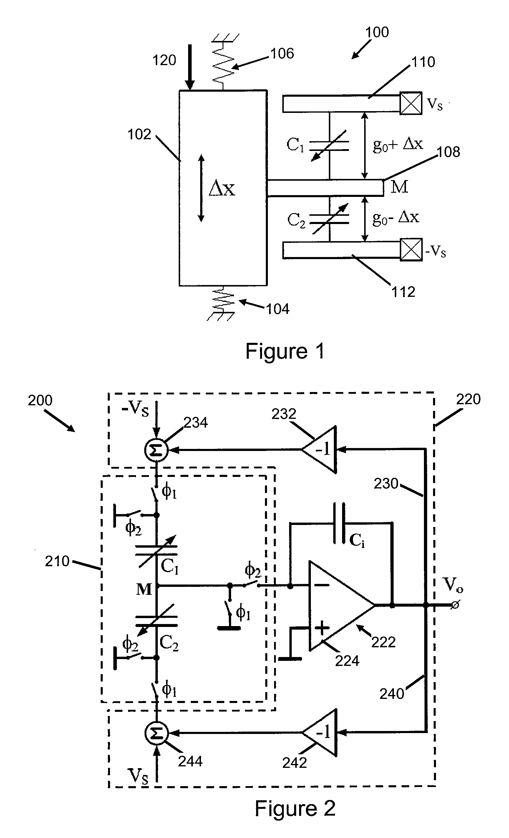
[0027]Using active circuits to implement the summing nodes in FIG. 2 provides better equalization of the absolute charge on the transducer capacitors C1 and C2, which reduces the impact of the readout or interface circuit on the sensor. However, using active amplifiers for implementing the summing nodes introduces unwanted disturbances, noise and offset, to the signals they process. Attenuating the disturbances introduced by the active amplifiers reduces the impact of these disturbances on the output signal.

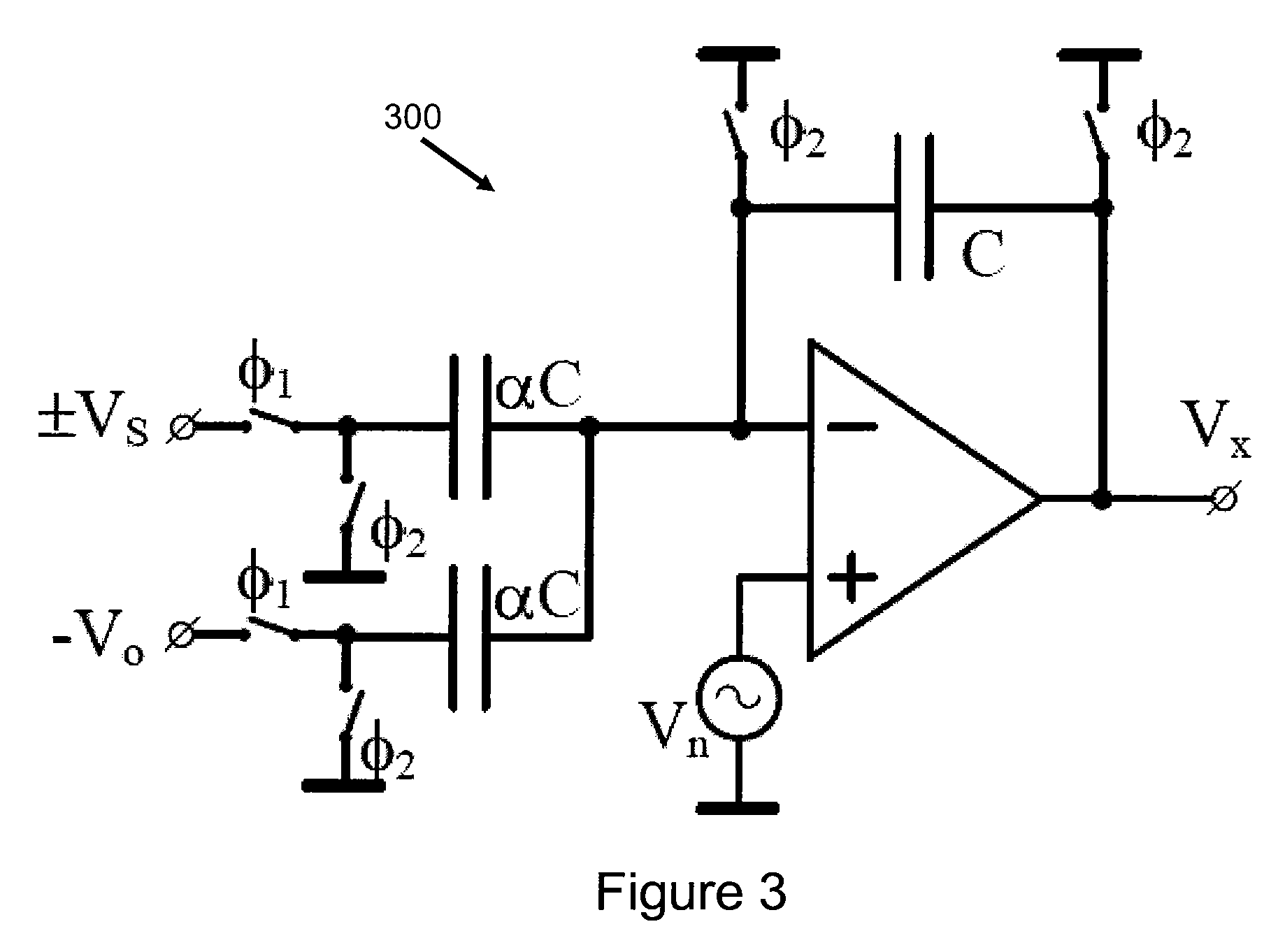
[0028]FIG. 3 shows an exemplary implementation of a summing amplifier 300 implemented by an active circuit that accepts input signals VS and V0 and produces an output signal VX. In this case, VS is the system reference voltage and V0 is the system output voltage. The summing amplifier 300 also introduces an unwanted disturbance signal Vn that is included in the output signal VX. The offset cancellation has been omitted for simplicity. Conventional analysis of switched-capacitor a...


PUM

PropertyMeasurementUnit
polarityaaaaaaaaaa
voltageaaaaaaaaaa
accelerationaaaaaaaaaa

Abstract

A capacitive transducer and a readout circuit for processing a signal from a capacitive transducer. The readout circuit includes a high gain circuit element, two summing amplifiers and two feedback path. The high gain circuit element generates an amplified transducer signal, and the summing amplifiers sum the amplified transducer signal with a positive reference voltage and the negative reference voltage, respectively, to generate a first summation signal and a second summation signal. The feedback paths feed back the summation signals to the transducer. Output circuitry generates an output signal based on the summation signals. The high gain circuit element can be a switched capacitor integrator. The output circuitry can generates the output signal based on the first and second summation signals.

Description

CROSS REFERENCE TO RELATED APPLICATIONS[0001]This application is a continuation of U.S. patent application Ser. No. 13 / 220,306, filed on Aug. 29, 2011, entitled “Readout Circuit for Self-Balancing Capacitor Bridge,” which is incorporated herein by reference.BACKGROUND OF THE INVENTION[0002]This patent relates to capacitive transducers, and more particularly to techniques for attenuation of unwanted disturbances in capacitive transducers.[0003]Transducers convert a general physical quantity (for example, acceleration, pressure, etc.) to quantities that can be processed by electronic circuits. In particular, capacitive transducers produce a change of capacitance, corresponding to the magnitude of the measured input signal. Readout circuits for capacitive transducers transform the capacitance change produced by the transducer to an electrical signal. In the process, the circuits apply voltage waveforms to the transducer electrodes.[0004]A capacitive accelerometer, a capacitive transduc...

Claims


Application Information

Patent Timeline
Patent Type & Authority Applications(United States)
IPC IPC(8): G01R27/26H05K3/30
CPCG01D5/24Y10T29/4913G01L1/144G01P15/125
Inventor PETKOV, VLADIMIRBALACHANDRAN, GANESH
Owner ROBERT BOSCH GMBH
Why Eureka
Try Eureka