
Light-reflective anisotropic conductive adhesive agent, and light emitting device

Active Publication Date: 2013-02-28
DEXERIALS CORP
View PDF1 Cites 7 Cited by
  • Summary
  • Abstract
  • Description
  • Claims
  • Application Information

AI Technical Summary

Benefits of technology

The present invention introduces a light-reflective anisotropic conductive adhesive and light-emitting device that prevents cracks and achieves higher conduction reliability by adding light-reflective acicular insulating particles.

Problems solved by technology

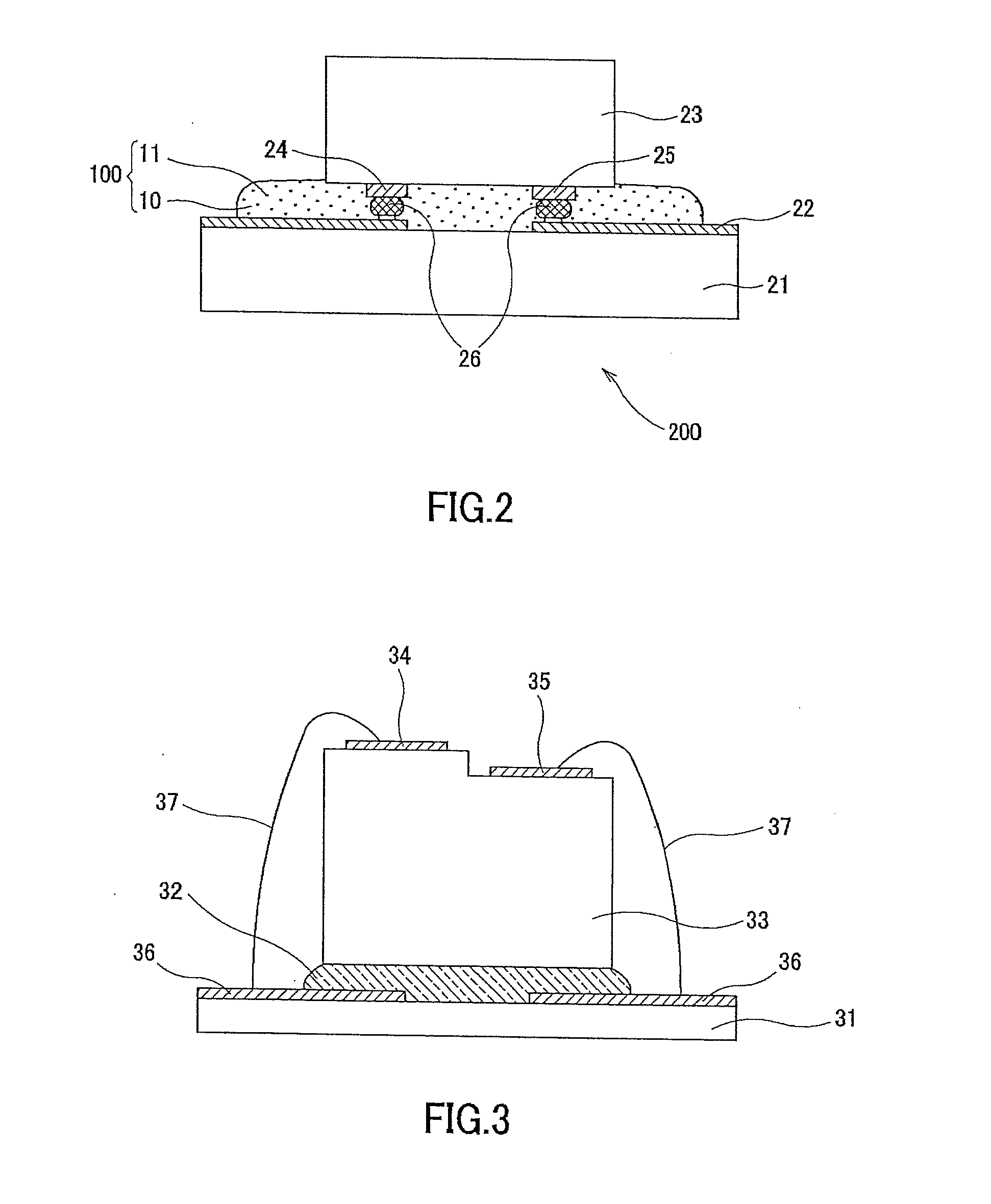
Moreover, the adhesion process with the die bond adhesive 32 is based on oven curing, thereby disadvantageously taking time for manufacture.
Furthermore, light may be diffused or absorbed inside the conductive paste 37, thereby decreasing luminous efficiency of the LED element 33.
However, this technology of Patent Document 1 has disadvantages such that the number of manufacturing processes of the light-emitting device is increased and cost is inevitably increased.

Method used


Image

  • Light-reflective anisotropic conductive adhesive agent, and light emitting device
  • Light-reflective anisotropic conductive adhesive agent, and light emitting device
  • Light-reflective anisotropic conductive adhesive agent, and light emitting device

Examples


example 1

[0077](Fabrication of Anisotropic Conductive Adhesive)

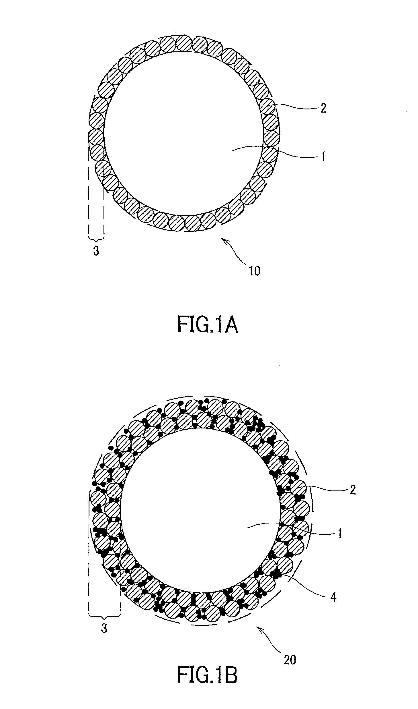
[0078]White acicular inorganic particles and conductive particles each having a surface of a globular resin plated with gold (a particle diameter of 5 μm) were mixed into a thermosetting resin composite made of an epoxy curing-based adhesive (an adhesive binder having CE2021P-MeHHPA as a main component), thereby fabricating an anisotropic conductive adhesive. The amount of addition of the white acicular inorganic particles was 12.0 volume % with respect to the thermosetting resin composite. As the white acicular inorganic particles, titanium dioxide (TiO2) whiskers having a long-direction particle diameter of 1.7 μm and a short-direction particle diameter of 0.13 μm (an aspect ratio of 13.1) were used. Also, the amount of addition of the conductive particles was 10 mass % with respect to the thermosetting resin composite.

[0079](Evaluation of Optical Reflectance)

[0080]A white board was coated with the fabricated anisotropic conduc...

example 2

[0089]As the white acicular inorganic particles, zinc oxide (ZnO) whiskers (pana-tetra WZ-05F1 manufactured by AMTEC CO., LTD.) having a long-direction particle diameter of 50 μm and a short-direction particle diameter of 3 μm (an aspect ratio of 16.7) were used. Other than that, a process similar to that of Example 1 was performed.

example 3

[0090]As the white acicular inorganic particles, potassium titanate whiskers (TISMO series manufactured by Otsuka Chemical Co., Ltd.) having a long-direction particle diameter of 20 μm and a short-direction particle diameter of 0.6 μm (an aspect ratio of 33.3) were used. Other than that, a process similar to that of Example 1 was performed.


PUM

PropertyMeasurementUnit
Percent by volumeaaaaaaaaaa
Temperatureaaaaaaaaaa

Abstract

A light-reflective anisotropic conductive adhesive and light-emitting device capable of maintaining luminous efficiency of a light-emitting element and preventing the occurrence of a crack to obtain conduction reliability are provided. The light-reflective anisotropic conductive adhesive contains a thermosetting resin composite, conductive particles, and a light-reflective acicular insulating particles. These light-reflective acicular insulating particles are inorganic particles of at least one type selected from the group including titanium oxide, zinc oxide, and titanate.

Description

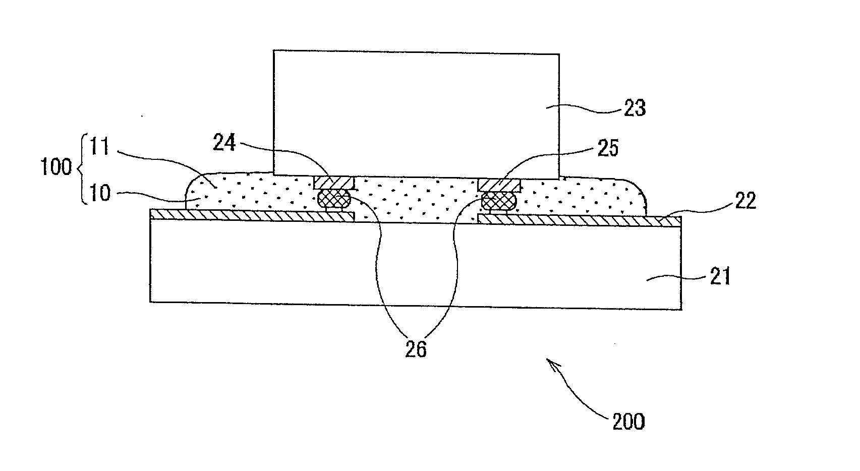
FIELD OF THE INVENTION[0001]This invention relates to a light-reflective anisotropic conductive adhesive to be used for anisotropic conductive connection of a light-emitting element onto a wiring board, and a light-emitting device having a light-emitting element mounted on a wiring board by using this light-reflective anisotropic conductive adhesive.[0002]The present application claims priority rights to JP Patent Application 2010-092672 filed in Japan on Apr. 13, 2010, which is hereby incorporated by reference.BACKGROUND OF THE INVENTION[0003]Conventionally, a light-emitting device using a light-emitting element such as a light-emitting diode (LED) has been widely used. FIG. 3 to FIG. 5 each depict an example of structure of a light-emitting device of an old type. In manufacture of the light-emitting device depicted in FIG. 3, an LED element 33 is bonded onto a substrate 31 with a die bond adhesive 32, and a p electrode 34 and an n electrode 35 on an upper surface of the LED elemen...

Claims


Application Information

Patent Timeline
IPC IPC(8): H01B1/20H01L33/60
CPCH01L24/06H01L24/17H01L24/29H01L24/32H01L24/48H01L24/83H01L33/405H01L33/60H01L33/62H01L2224/29198H01L2224/29339H01L2224/32057H01L2224/48091H01L2224/48227H01L2224/49107H01L2224/73204H01L2224/73265H01L2224/83385H01L2224/83855H01L2224/92247H01L2924/01004H01L2924/01013H01L2924/01022H01L2924/01027H01L2924/01029H01L2924/0103H01L2924/01046H01L2924/01047H01L2924/01056H01L2924/01057H01L2924/01078H01L2924/01079H01L2924/01082H01L2924/014H01L2924/0781H01L2924/10157C08K3/22C09J9/02C09J11/04C08K9/06C08K2003/2296H01L2224/2919H01L2924/01005H01L2924/01006H01L2924/01019H01L2924/01033H01L2924/0665H01L2224/29101H01L2224/16225H01L2224/32225H01L2224/45144H01L2224/13339H01L2924/12041H01L2924/07811C08K2003/0831C08K3/08C08K2003/2241H01L2924/00014H01L2924/00H01L2924/3512H01L2924/00012C08K3/24H01L2924/181H01L2224/0401H01L24/73H01L24/45C08K7/08H01L24/49H01L2224/45015H01L2924/207C09J201/00H01L21/64H01L2924/01081
Inventor NAMIKI, HIDETSUGUKANISAWA, SHIYUKIUMAKOSHI, HIDEAKIISHIGAMI, AKIRA
Owner DEXERIALS CORP
Learn More