Anisotropic electrically conductive film and connection structure
an electrically conductive film and anisotropic technology, applied in the direction of film/foil adhesives without carriers, film/foil adhesives, conductors, etc., can solve problems such as connection resistance, and achieve the effects of reducing the effective mounting area, reducing the variation in the number of electrically conductive particles present within the rectangle, and reducing the number of electrically conductive particles
- Summary
- Abstract
- Description
- Claims
- Application Information
AI Technical Summary
Benefits of technology
Problems solved by technology
Method used
Image
Examples
examples 2 to 7
, Comparative Examples 2 to 5
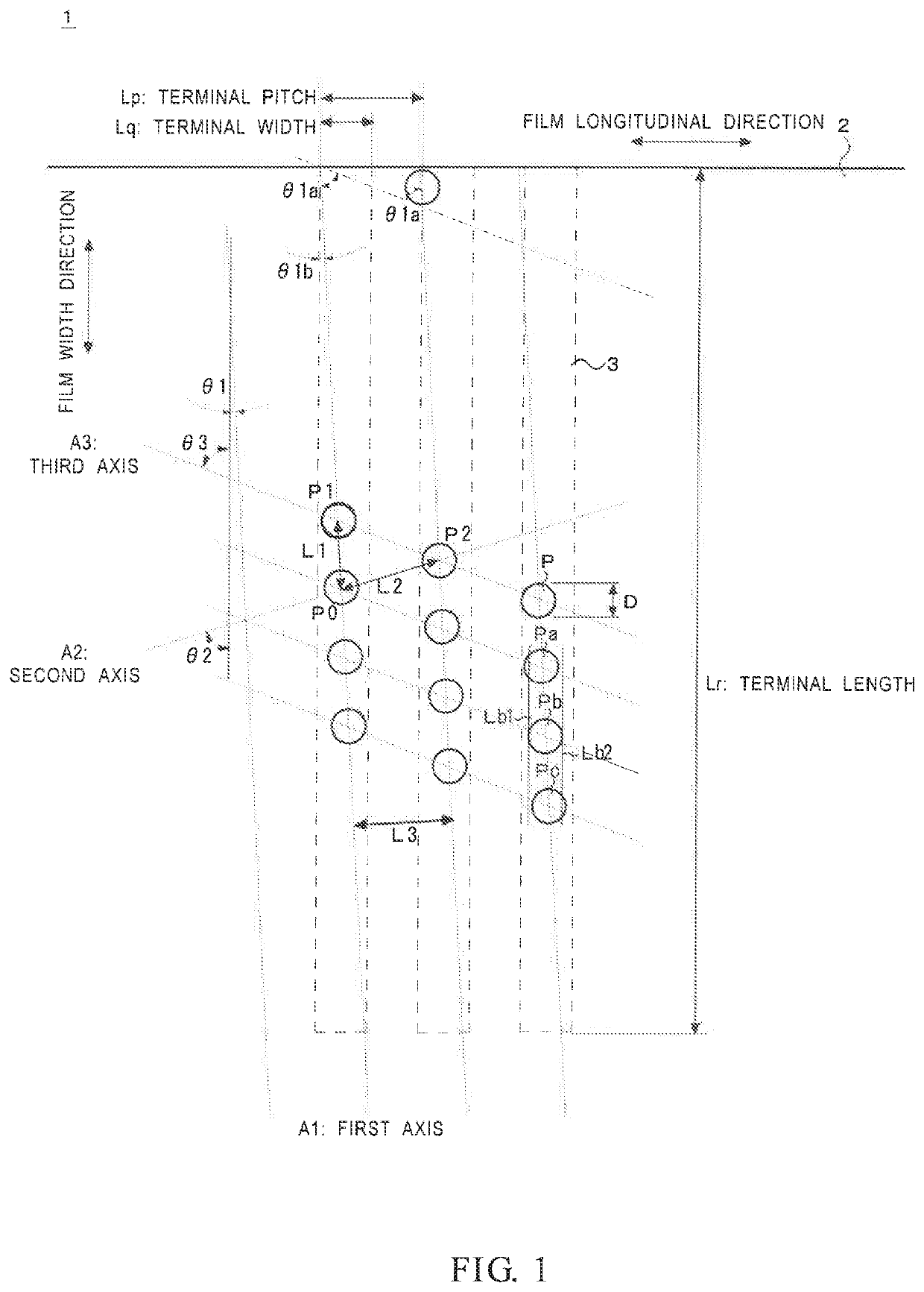
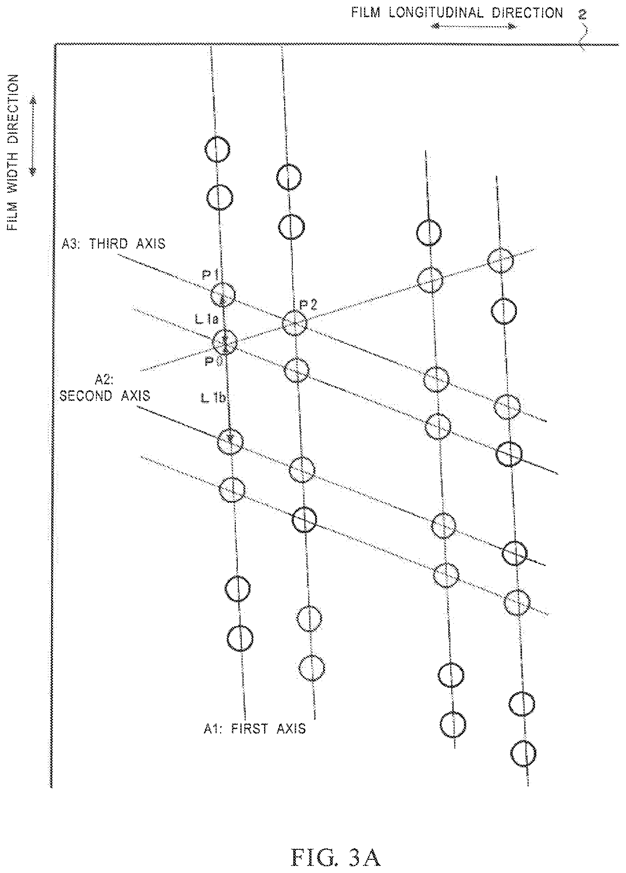
[0159]To investigate the influence of the arrangements of the electrically conductive particles on the conduction characteristics, anisotropic electrically conductive films for COG of Examples 2 to 7 and Comparative Examples 2 to 5 were produced in the same manner as in Example 1 except that the arrangements of the electrically conductive particles were varied as shown in Table 2. The arrangement patterns of electrically conductive particles of the examples and the comparative examples were as illustrated in the drawings.
[0160]Connected objects for evaluation were produced using the obtained anisotropic electrically conductive films, and evaluations of the films were made in the same manner as in Example 1 for (a) initial conduction resistance, (b) indentation, and (c) particle capturing capability. In addition, (d) conduction reliability and (e) short-circuit occurrence rate were evaluated in the following manner.
[0161]These results, together with the r...
examples 8 to 10
[0170]To investigate the influence of the arrangements of the electrically conductive particles on the conduction characteristics, anisotropic electrically conductive films for FOG of Examples 8 to 10 were produced in the same manner as in Example 1 except that the arrangements of the electrically conductive particles were varied as shown in Table 3.
[0171]In this case, the connected objects for evaluation used were the following evaluation flexible printed circuit substrate and glass substrate, which were connected together with an effective mounting area of 100% or 80% (180° C., 80 MPa, 5 seconds).
[0172]Herein, the connected objects for evaluation having an effective mounting area of 100% refers to objects having no misalignment between the flexible printed circuit substrate and the glass substrate or having a misalignment range of not greater than 2%, and those of 80% refers to objects having a misalignment range of 20%.
[0173]Flexible printed circuit substrate for evaluation (FPC)...
PUM
| Property | Measurement | Unit |
|---|---|---|
| length | aaaaa | aaaaa |
| length | aaaaa | aaaaa |
| length | aaaaa | aaaaa |
Abstract
Description
Claims
Application Information
 - R&D
- Intellectual Property
- Life Sciences
- Materials
- Tech Scout
- Unparalleled Data Quality
- Higher Quality Content
- 60% Fewer Hallucinations
Browse by: Latest US Patents, China's latest patents, Technical Efficacy Thesaurus, Application Domain, Technology Topic, Popular Technical Reports.
© 2025 PatSnap. All rights reserved.Legal|Privacy policy|Modern Slavery Act Transparency Statement|Sitemap|About US| Contact US: help@patsnap.com


