
Conductive particle filled polymer electrical contact

a polymer and conductive technology, applied in the field of electrical connectors, can solve the problems of particle to particle electrical contact being interrupted or glitched, contact risk is reduced, and the reliability of conductive filled elastomer contact is enhanced, and the risk of glitches is reduced

Inactive Publication Date: 2008-12-16
INT BUSINESS MASCH CORP
View PDF4 Cites 3 Cited by
  • Summary
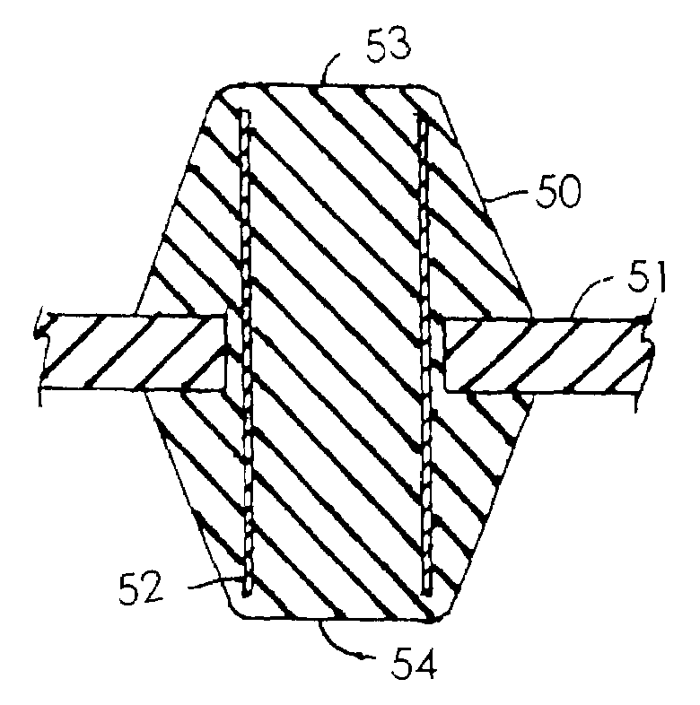
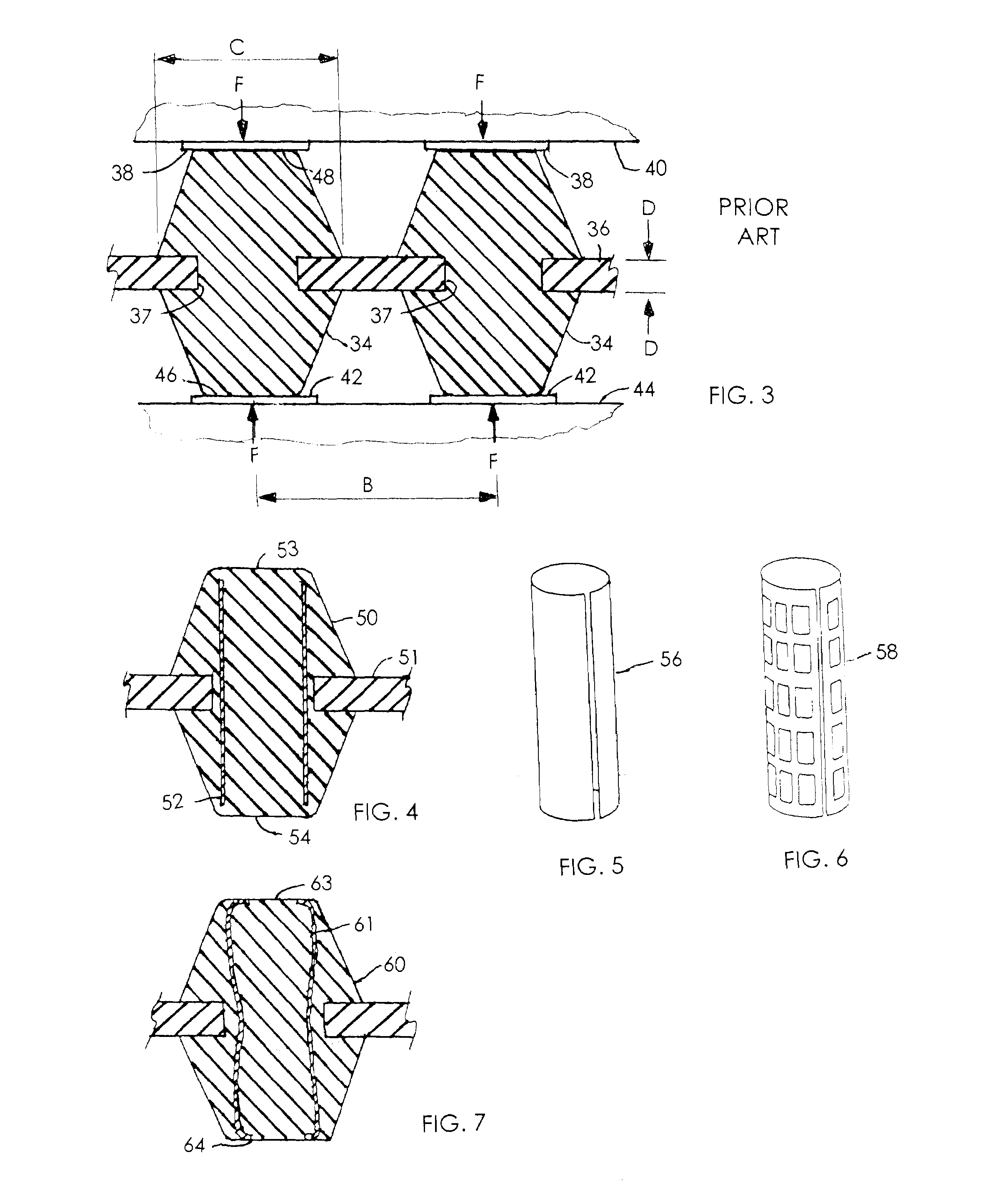
  • Abstract
  • Description
  • Claims
  • Application Information

AI Technical Summary

Benefits of technology

[0006]Conductive particle filled polymer contacts are a common contact structure of choice. Such contacts are subject to the occasional occurrence of a glitch caused by an interruption of particle to particle electrical contact. Although the occurrence of a glitch is infrequent, in a grid including thousands of contacts which must always provide a reliable electrical path, even rare occurrences are not acceptable. A typical condition that may cause a glitch is the difference between the coefficients of thermal expansion of the module and the printed circuit board which are being interconnected. The differing coefficients can introduce a substantial lateral shear force which can cause particle to particle electrical contact to be interrupted or glitch. The present invention discloses a means to reduce the risk of glitching.
[0007]The glitching problem is reduced and the reliability of the conductive filled elastomer contact is enhanced by a conductive frame which is introduced into the mold cavity, prior to the molding of the contact, as an insert extending through the carrier aperture to provide a conductor extending from adjacent one contact surface on the contact body to the other contact surface on the contact body. The reliability of a CFP contact can be estimated based on the number of particle contact interfaces in parallel versus the number of particle contacts in series. With a conductive filled polymer there are many contacts across any given cross section of the CFP contact. For contacts having the same height and diameter with particles of uniform size, the ratio of the parallel to series contacts would be one or the contact reliability would be that of a single interface. However, since a contact bodies height is greater than the diameter, the ratio will actually be greater than one meaning the contact reliability has actually been reduced (i.e. the failure rate has been increased).
[0008]Use of a conductive frame reduces the number of series electrical connections between the contact upper and lower surfaces which engage the device contact surfaces to be interconnected. The presence of a conductive frame extending through the length of the contact provides a reliable electrical path through the length of the contact. The path between the contact surfaces being connected (the height of the connector) can be 8 to 10 times the length of the path to the conductive frame. The short particle to particle electrical path to the conductive frame increases contact reliability by effectively reducing the number of connector particle interfaces through the contact height. This reduces the contact bulk resistance through the contact height.
[0009]The conductive frame does not have to have spring properties since the contact body elastic properties are controlled by the elastomer properties. This means the electrical conductivity of the conductive frame base material can be pure copper or other highly conductive malleable material. Inclusion of a conductive frame increases the reliability achieved by reducing the dependence on particle surface contacts and further enables smaller contact cross sectional size and closer contact spacing.

Problems solved by technology

Such contacts are subject to the occasional occurrence of a glitch caused by an interruption of particle to particle electrical contact.
Although the occurrence of a glitch is infrequent, in a grid including thousands of contacts which must always provide a reliable electrical path, even rare occurrences are not acceptable.
A typical condition that may cause a glitch is the difference between the coefficients of thermal expansion of the module and the printed circuit board which are being interconnected.
The differing coefficients can introduce a substantial lateral shear force which can cause particle to particle electrical contact to be interrupted or glitch.
However, since a contact bodies height is greater than the diameter, the ratio will actually be greater than one meaning the contact reliability has actually been reduced (i.e. the failure rate has been increased).
This reduces the contact bulk resistance through the contact height.

Method used


Image

  • Conductive particle filled polymer electrical contact
  • Conductive particle filled polymer electrical contact
  • Conductive particle filled polymer electrical contact

Examples


Embodiment Construction

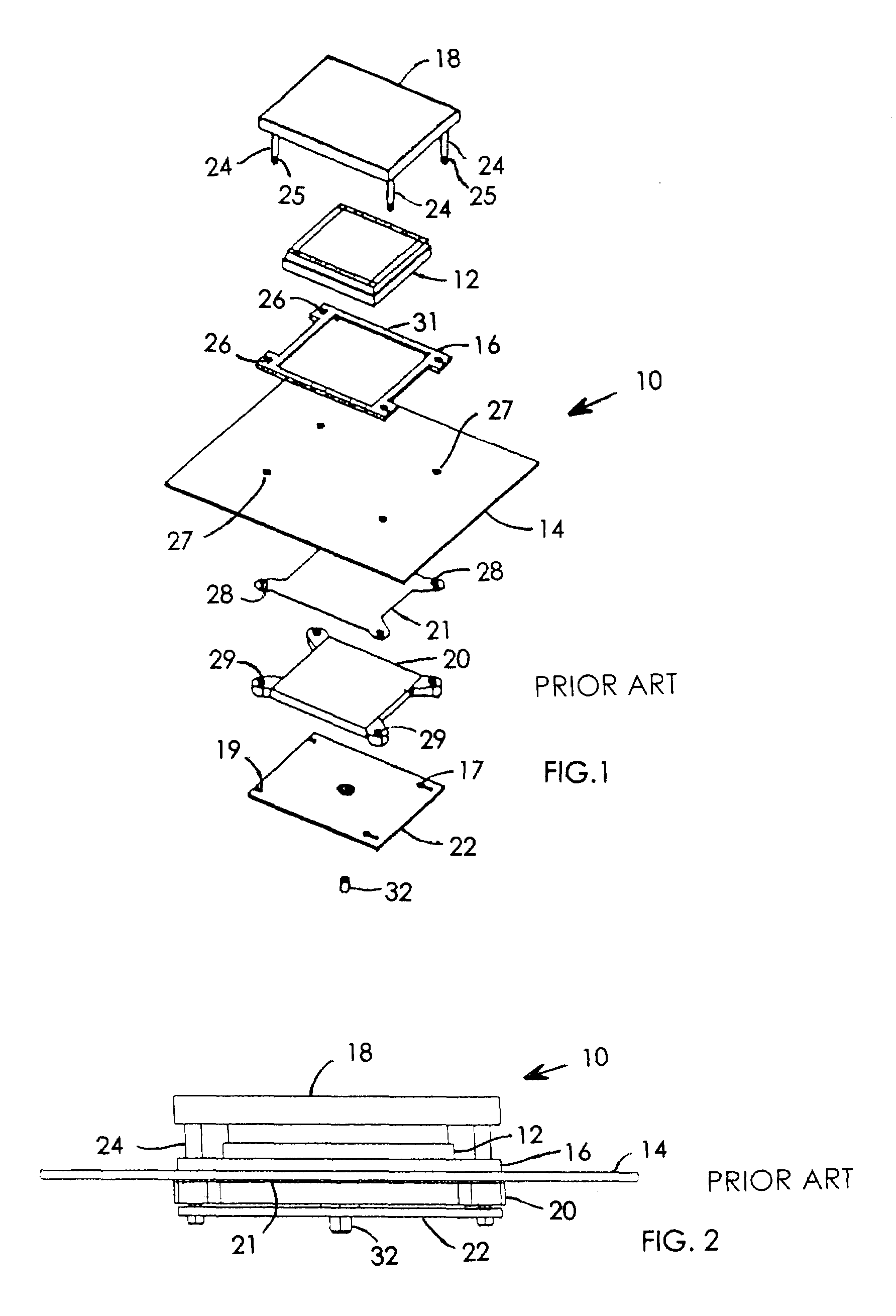
[0016]FIGS. 1 and 2 illustrate a typical land grid array (LGA) socket assembly 10. FIG. 1 is an exploded view of the assembly and FIG. 2 is an assembled view of the elements of FIG. 1. The LGA module 12 carries a pattern or grid of contact surfaces on the lower surface which confronts the printed circuit board 14 that carries a pattern or grid of contact surfaces adapted to be aligned with and electrically connect the module to the circuits on the printed circuit board. The electrical connection is effected by an LGA interposer with a pattern or grid of contacts which are aligned between the LGA module contact surfaces and the printed circuit board contact surfaces. Each interposer contact extends through and is captured at an aperture in the electrically insulating interposer carrier substrate and is conductive and compressible to establish an electrically conductive path between the confronting contact surfaces presented by the module 12 and the printed circuit board 14. A rigid u...


PUM


Abstract

A conductive filled polymer contact which is molded at an aperture through a carrier sheet includes an elongated conductive frame introduced prior to the molding process as an insert which is held captive in the molded contact and which extends from at or near the upper contact surface, through the aperture and terminates at the opposite end at or near the lower contact surface to provide a continuous conductive path through the length of the contact, whereby the sequence of particle to particle interfaces within the molded polymer contact is reduced in number to increase reliability.

Description

FIELD OF THE INVENTION[0001]This invention pertains to electrical connectors and more particularly to conductive particle filled elastomer contacts mounted on an interposer.BACKGROUND OF THE INVENTION[0002]The performance requirements of modern electronic systems has required the use of increased interconnect contact densities. For high density connector array applications, a common connector of choice is the land grid array (LGA) connector to achieve direct electrical interconnection between such typical devices as a module and a printed circuit board. Electrical engagement between the contact array of the module and the mating contact array presented by the circuit board is enabled by a contact carrying interposer, wherein connection is effected by aligning the interposer contact array with the respective mating surfaces of the module and circuit board and applying a clamping force to mechanically compress the interposer between module and circuit board.[0003]The contacts mounted ...

Claims


Application Information

Patent Timeline
Patent Type & Authority Patents(United States)
IPC IPC(8): G01R31/02H01R12/71
CPCH01R13/2414H05K7/1061H01R12/7082
Inventor BRODSKY, WILLIAM LOUIS
Owner INT BUSINESS MASCH CORP
Learn More