Miller cycle engine

Inactive Publication Date: 2012-11-08
MITSUBISHI HEAVY IND LTD
View PDF30 Cites 15 Cited by
  • Summary
  • Abstract
  • Description
  • Claims
  • Application Information

AI Technical Summary

Benefits of technology

[0016]This invention has been made in view of the aforementioned problems, and an object of the invention is to provide a miller cycle engine which improves the pumping work formed by an intake stroke and an exhaust stroke by increasing only boost pressure or by increasing the boost pressure more than increase in exhaust pressure, and also improves the reliability of mechanical strength and thermal load of the engine body by maintaining the maximum in-cylinder pressure at substantially the same level as that before increasing of the boost pressure.

Problems solved by technology

Therefore, the resulting pumping work is not improved significantly in comparison with that before increasing the turbo pressure (the shaded area in FIG. 7 only shifts up by h).
As a result, the maximum in-cylinder pressure (Pmax) may exceed the allowable maximum pressure, which will adversely affect the mechanical strength and thermal load of the engine body.
However, neither of the aforementioned Patent Documents 1 and 2 discloses a technique for improving the thermal efficiency by increasing pumping work formed by an exhaust stroke and an intake stroke in a miller cycle engine.
Furthermore, as already described with reference to FIG. 7, improvement in thermal efficiency by the pumping work cannot be obtained by merely raising the turbo pressure.
Moreover, this may induce a problem that the rising of the maximum in-cylinder pressure (Pmax) causes an adverse effect on mechanical strength and thermal load of the engine body.

Method used


Image

  • Miller cycle engine
  • Miller cycle engine
  • Miller cycle engine

Examples


first embodiment

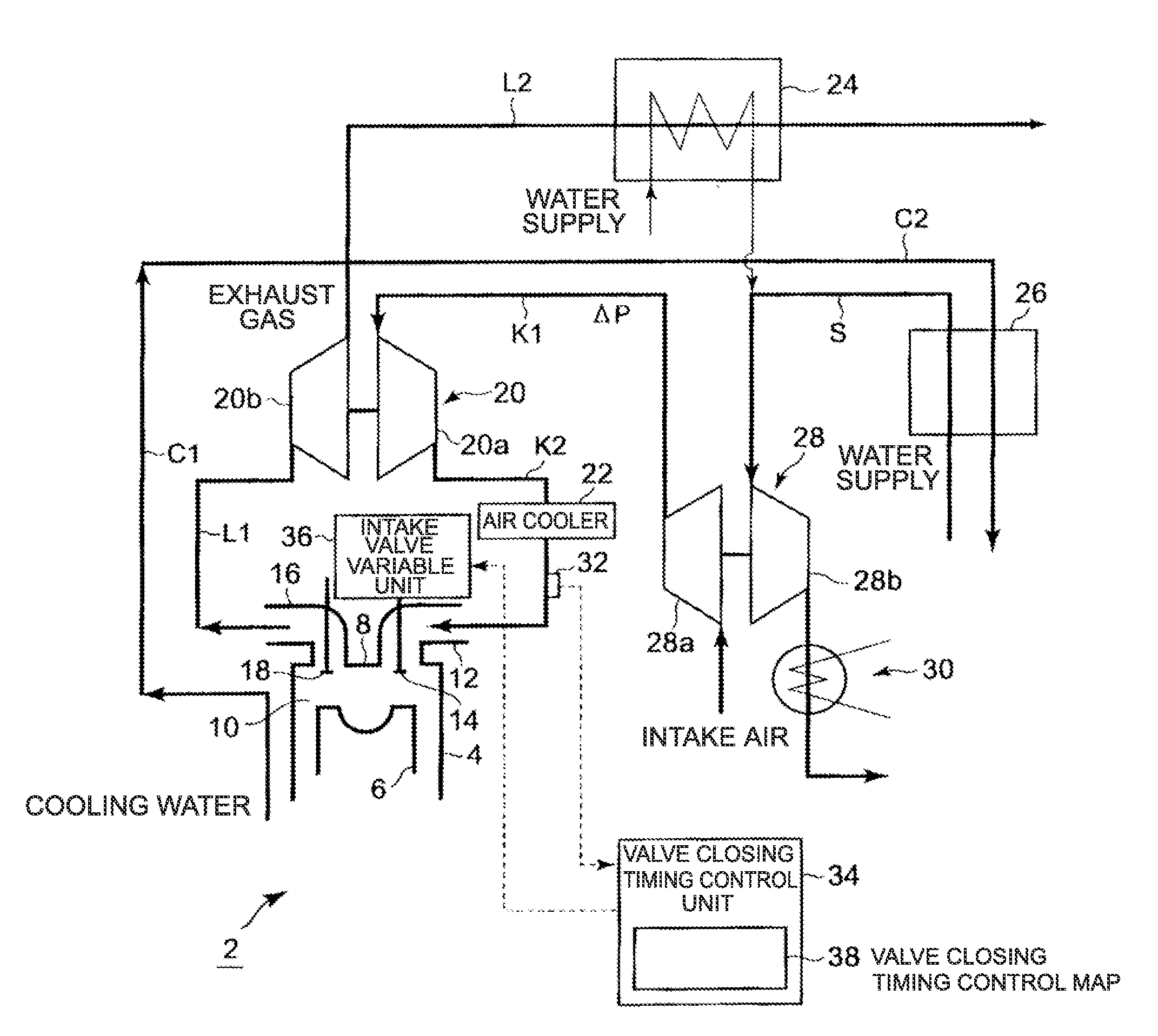
[0037]FIG. 1 is a general configuration diagram of a miller cycle engine (hereafter, simply referred to as the engine) 2 according to a first embodiment of this invention.

[0038]Although, in FIG. 1, the engine 2 is shown as a four cycle gas engine for an illustrative purpose, the engine is not limited to a gas engine.

[0039]There are provided in a cylinder 4 of the engine body, a piston 6 which is fitted reciprocally and slidably in the cylinder, and a crank shaft which converts reciprocating motion of the piston 6 into rotation via a connecting rod (not shown). The engine body further has a combustion chamber 10 defined between the upper face of the piston 6 and an inner surface of a cylinder head 8, an intake port 12 connected to the combustion chamber 10, and an intake valve 14 for opening and closing the intake port 12. The engine body further has an exhaust port 16 connected to the combustion chamber 10 and an exhaust valve 18 for opening and closing the exhaust port 16.

[0040]Whi...

second embodiment

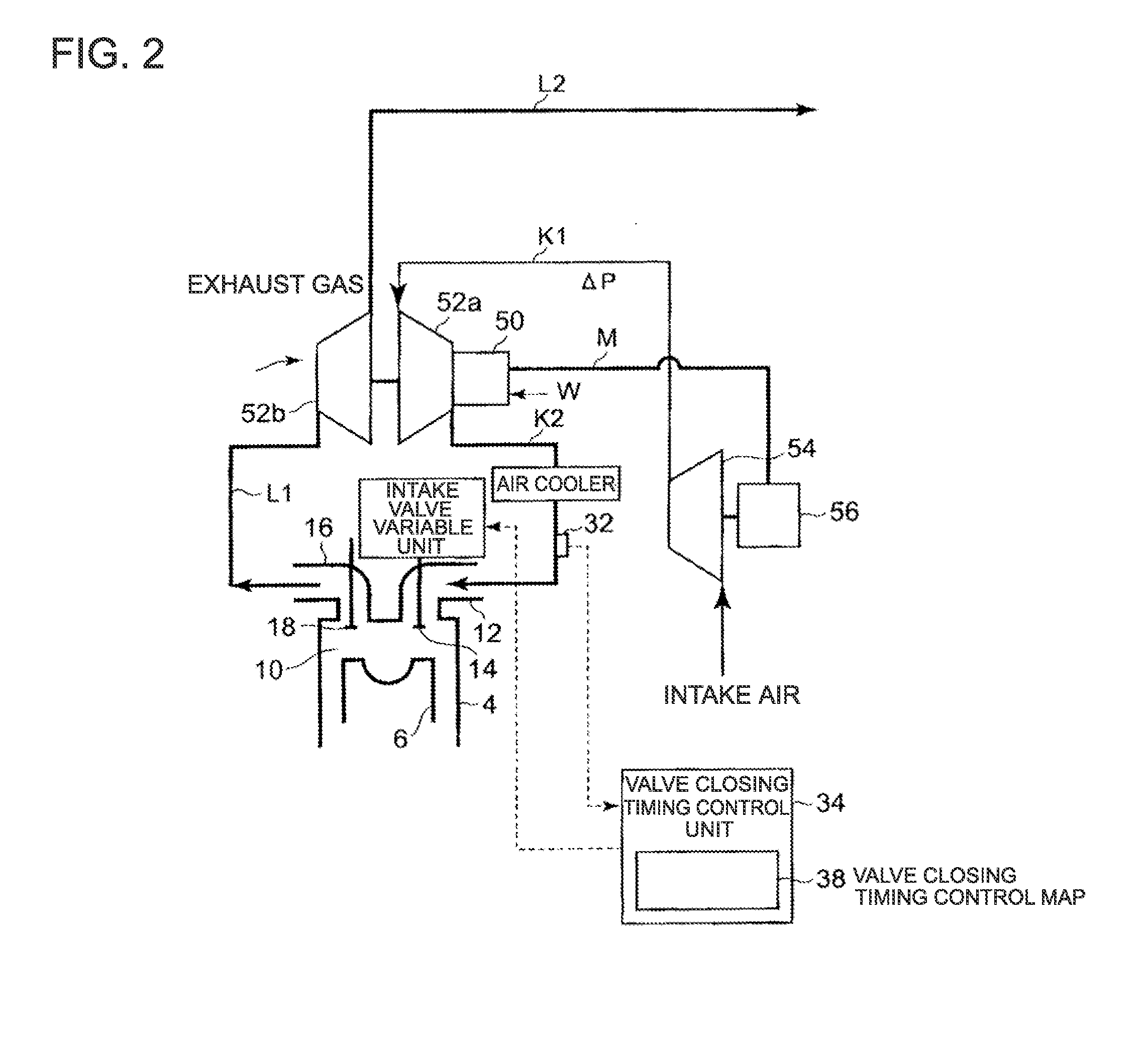
[0066]A second embodiment of the invention will be described with reference to FIG. 2.

[0067]The second embodiment uses electric power generated by utilizing exhaust gas as regenerative energy of an engine.

[0068]As shown in FIG. 2, a turbocharger is formed by a hybrid turbocharger 52 having a generator motor 50 incorporated therein.

[0069]An additional boost pressure is generated by driving a supply air blower 54 provided on an air supply channel K1 upstream of the hybrid turbocharger 52 with use of electric power generated by utilizing exhaust gas.

[0070]The hybrid turbocharger 52 is composed of a compressor unit 52a and a turbine unit 52b. The compressor unit 52a has the generator motor 50 incorporated therein. Electric power is generated by rotation of the compressor unit 52a, and the generated power is supplied to a blower motor 56 for driving a supply air blower 54 through a power supply line M. Control of rotation speed of the blower motor 56 is performed with use of an inverter ...

third embodiment

[0074]A third embodiment of the invention will be described with reference to FIG. 3. In this third embodiment, a pre-turbocharger 60 is driven by using exhaust gas as regenerative energy of an engine. This means that the pre-turbocharger 60 is provided in place of the steam turbine 28 described in the first embodiment.

[0075]As shown in FIG. 3, exhaust gas, which has passed through the turbine unit 20b of the turbocharger 20, flows into a turbine unit 60b of the pre-turbocharger 60 to drive a compressor unit 60a of the pre-turbocharger 60 provided coaxially with the turbine unit 60b and pressurize supply air. The compressor unit 60a of the pre-turbocharger 60 and the compressor unit 20a of the turbocharger 20 forms a two-stage turbocharging system so that the supply air pressurized by the compressor unit 60a is supplied to the compressor unit 20a of the turbocharger 20 to be further pressurized thereby.

[0076]An air cooler 62 is provided on an air supply channel K1 connecting the com...


PUM


Abstract

Provided is a miller cycle engine in which the thermal efficiency is improved by increasing boost pressure, while the reliability of mechanical strength and thermal load of the engine body is secured by maintaining a maximum in-cylinder pressure. The mirror cycle engine includes an intake valve variable unit (36) for controlling timing to open or close an intake valve (14), a steam. turbine (28) serving as a boost pressure adding device which adds an additional boost pressure to the boost pressure increased by a turbocharger (20) so as to increase only the boost pressure, or so as to increase the boost pressure by the additional boost pressure that is larger than increase in exhaust pressure, and a valve closing timing control unit (34) which advances more the timing to close the intake valve (14) as the additional boost pressure added by the steam turbine (28) becomes higher so as to maintain the boost pressure at substantially the same level as a maximum in-cylinder pressure before adding the additional boost pressure.

Description

TECHNICAL FIELD[0001]This invention relates to a miller cycle engine which is configured to close an intake valve at a timing earlier or later than the bottom dead center to make a compression ratio lower than an expansion ratio, and in particular relates to a technique to improve the thermal efficiency of the miller cycle by increasing boost pressure.BACKGROUND ART[0002]A miller cycle engine is effective for avoiding occurrence of knocking and for realizing high thermal efficiency by closing an intake valve at a timing earlier or later than the bottom dead center to keep a compression ratio of the engine lower than an expansion ratio. A miller cycle engine is also known as being able to realize a high expansion ratio and to utilize combustion energy more efficiently as torque by sufficiently expanding combustion gas.[0003]In FIG. 7, the solid line indicates a P-V graph, which is a P-V graph of an internal combustion engine provided with a turbocharger. The P-V graph indicates an ea...

Claims


Application Information

Patent Timeline
IPC IPC(8): F02B37/12F02B33/44
CPCF01K23/065F02B33/40F02D13/0269Y02T10/144Y02T10/142Y02T10/16Y02T10/12F02B37/013F02B41/04F02B29/0406F02B37/04F02D13/0215F02D15/04F02D23/00F02B2275/32F01N5/02F01K23/06F02D13/02F02D15/00
Inventor ISHIDA, MICHIYASUODA, KENJIRONAMEKAWA, SHOJI
Owner MITSUBISHI HEAVY IND LTD
Why Eureka
Try Eureka