
Methods of using cyanine dyes for the detection of analytes

a technology of cyanine dye and analytes, applied in the field of detection of analytes, can solve the problems of fluid flow, and affecting the heat transfer rate of system equipment,

Inactive Publication Date: 2012-07-12
GENERAL ELECTRIC CO
View PDF5 Cites 4 Cited by
  • Summary
  • Abstract
  • Description
  • Claims
  • Application Information

AI Technical Summary

Benefits of technology

[0006]Chemical treatment of water is well developed and widely used. For example, it is known to add polyelectrolytes to the water to reduce scaling. One particularly useful polyelectrolyte is Coag139D (PMA, polymethacrylic acid); although other polyelectrolytes such as AEC, APES, and HPS-I are in use as well. However, the employment of polyelectrolytes in industrial water systems presents its own set of problems because the concentration of the polyelectrolytes in the water must be carefully monitored. For example, if too little of the polyelectrolytes is employed, scaling will occur. In contrast, if too high a concentration of the polyelectrolytes is employed, then the cost / performance efficiency of the system is adversely affected. As with other methods of chemically treating aqueous systems, there is an optimal concentration of treatment chemicals that should be maintained.

Problems solved by technology

Municipal or untreated water contain substances which can affect heat transfer, fluid flow or cause corrosion of system equipment.
The presence of these substances and any resulted scaling, biofouling and corrosion adversely affects the rate of heat transfer, and therefore the efficiency of the system.
However, the employment of polyelectrolytes in industrial water systems presents its own set of problems because the concentration of the polyelectrolytes in the water must be carefully monitored.
In contrast, if too high a concentration of the polyelectrolytes is employed, then the cost / performance efficiency of the system is adversely affected.
Generally, these methods require a complicated, multi-step operation procedure and are difficult to carry out in the field.
This method is lengthy and is susceptible to inaccuracies.

Method used


Image

  • Methods of using cyanine dyes for the detection of analytes
  • Methods of using cyanine dyes for the detection of analytes
  • Methods of using cyanine dyes for the detection of analytes

Examples


example 1

Cyanine Dyes for F—Cl Detection Using Aqueous IR-783

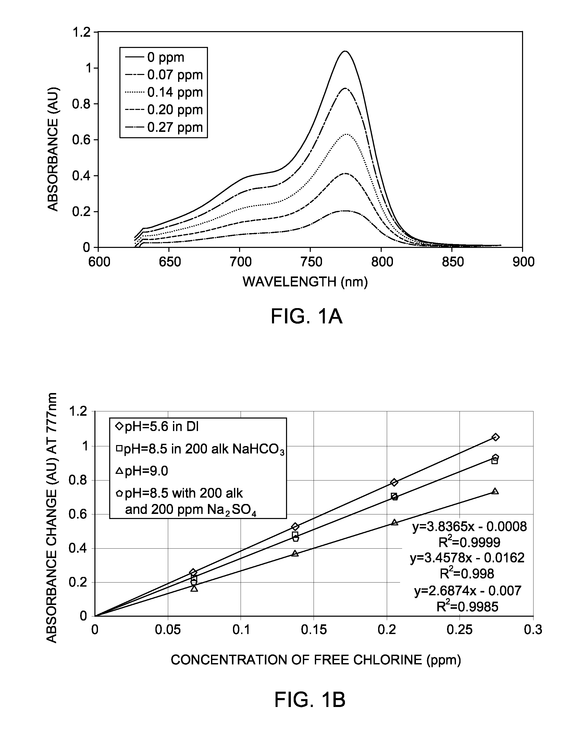
[0044]There are number of scenarios in which free chlorine (F—Cl) and / or total chlorine have be monitored at very low concentration. For example, reverse osmosis (R.O.) is a technique for removing dissolved solids (salts) from filtered raw water. It is used in a variety of industries to condition water for plant use, or as a step in the demineralization process. The continued performance of a reverse osmosis system depends upon the condition of the semipermeable membrane. When free chlorine concentration is higher than about 0.02 ppm, it can degrade many membrane materials, so the raw water is often dechlorinated prior to entering the R.O. system.

[0045]Since raw water can contain either free or total chlorine, it is important to determine which form of chlorine is present, and select the right chlorine monitoring equipment. Accordingly, supersensitive detection methods are highly desired for the protection of reverse osmosis membra...

example 2

Cyanine Dyes for F—Cl Detection using IR-783 in Solid pHEMA Film

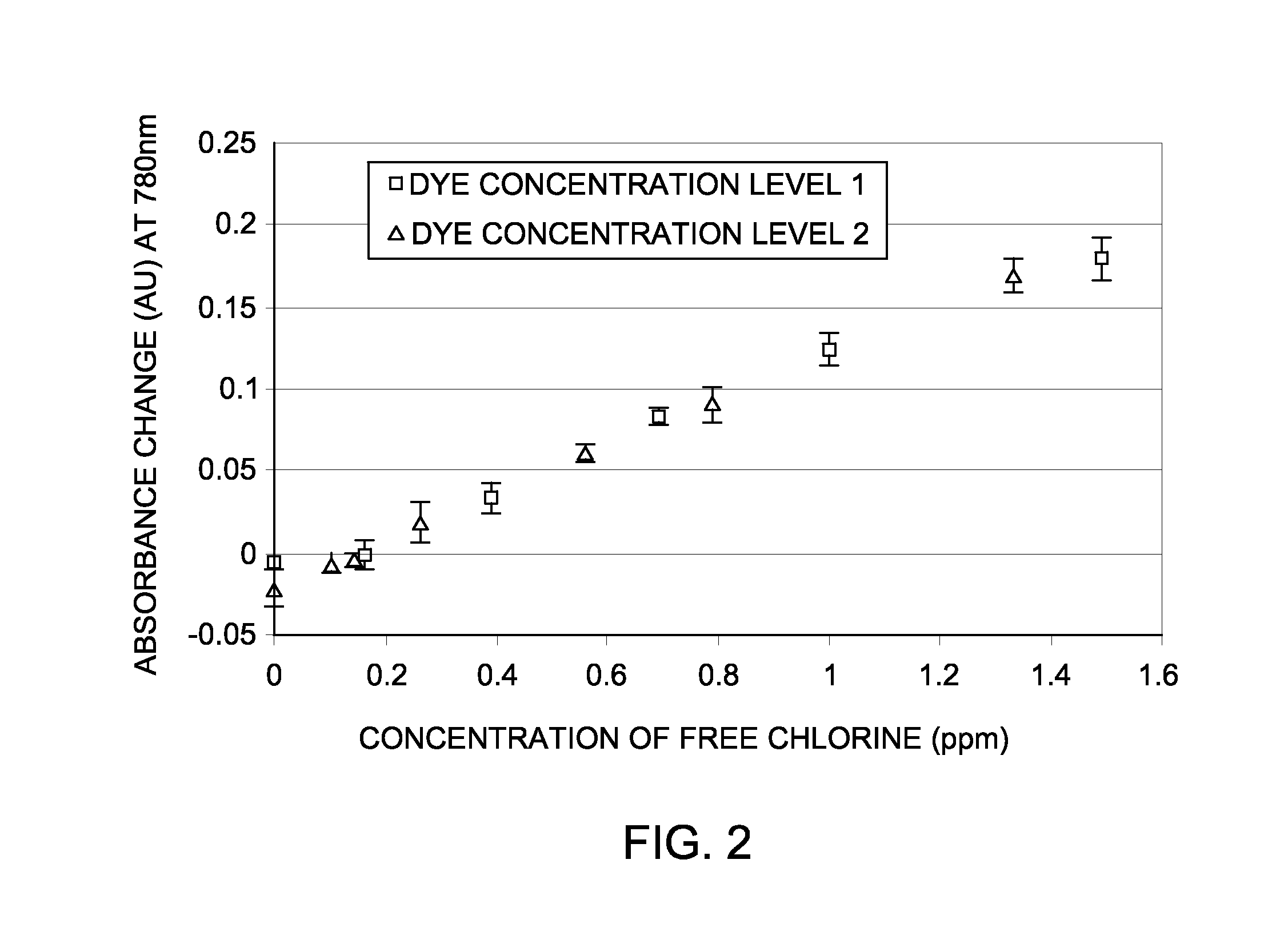
[0048]Applicants have also found that when IR-783 is incorporated into a film, the response to free-chlorine is identical to that of aqueous IR-783. In this example, the film was made from pHEMA stock in 2-methoxyethanol (or DM, or DM / PM mixture) containing IR-783 (5 mg to 20 mg per gram of pHEMA stock) by flow-coating. DM is di(ethylene glycol) monomethyl ether and PM is 1-Methoxy-2-Propanol. The dry film thickness could be from about 1 μm to about 20 μm. The film was assembled and exposed to standard F—Cl solutions and a TrueSense PWA reader was used to acquire the response. FIG. 2 shows the calibration curve obtained for IR-783 in pHEMA film at 780 nm. FIG. 2 was obtained by subtracting the absorbance of a samples containing free chlorine at known concentrations from the absorbance of a sample containing no free chlorine. In FIG. 2, dye concentration level 1 is 10 mg per 10 g of ink, and dye concentration level 2 is ...

example 3

Cyanine Dyes for T-Cl by IR-783 with KI

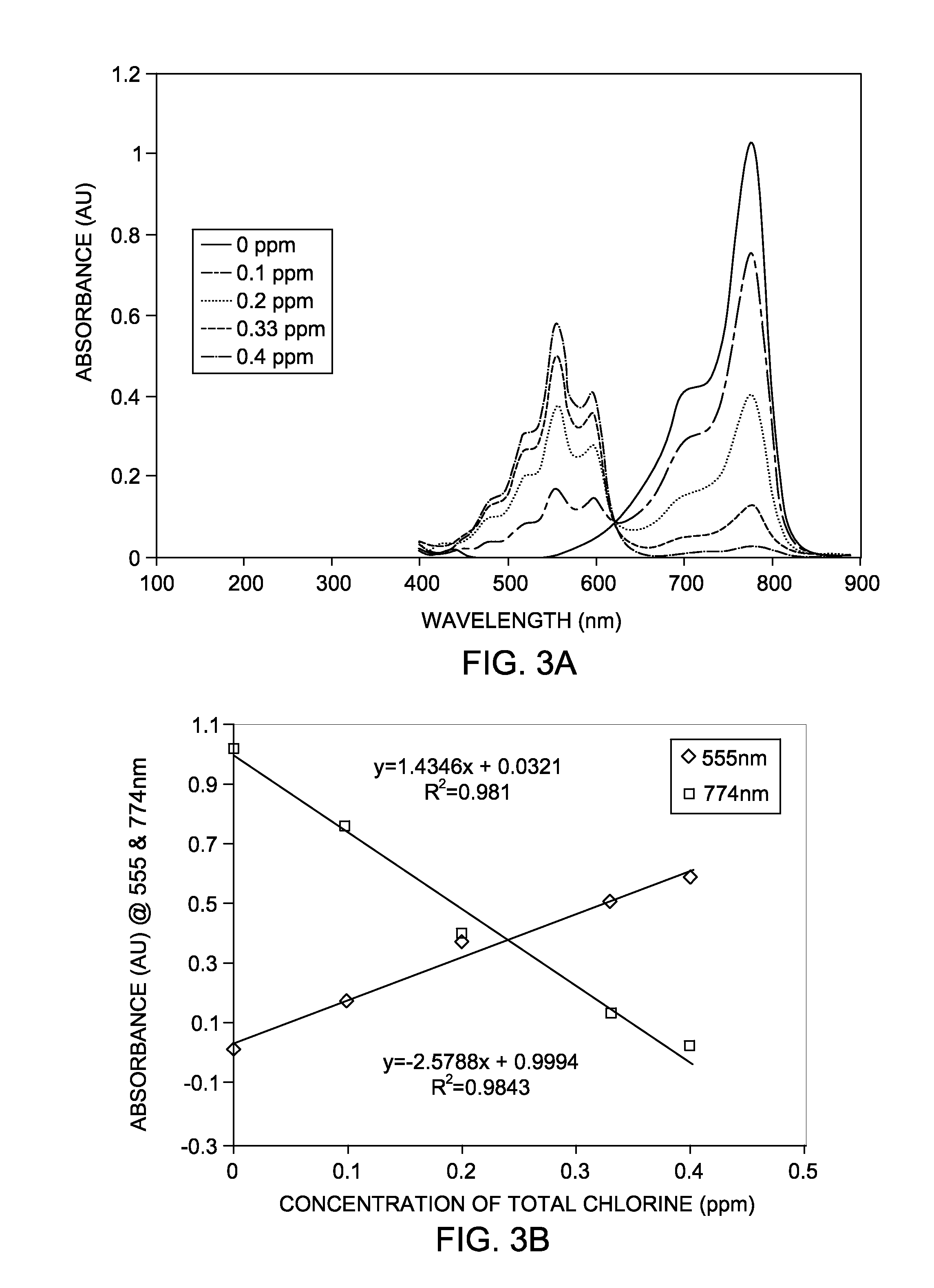
[0049]In this example, the total chlorine (T-Cl) is calculated using cyanine indicator dye, more specifically IR-783 in aqueous phase. T-Cl, the sum of both free and combined chlorine, can be determined by the DPD method after the addition of catalytic amounts of potassium iodide (KI) to the aqueous solution sample. In the DPD method, DPD (N,N-diethyl-p-phenylenediamine) is oxidized by chlorine, causing a magenta (red) color. The intensity of color is directly proportional to the chlorine concentration. For total chlorine, potassium iodide is added to the reaction to determine combined available chlorine forms and total chlorine. Chloramines oxidize the iodide to iodine; then the liberated iodine reacts with DPD to form the magenta color.

[0050]Monochloramine and dichloramine are very slowly reacts with cyanine dyes at near neutral pH. To quantify these species, the tests in this example were performed with iodide as catalyst. The iodide reacts ...


PUM

PropertyMeasurementUnit
thicknessaaaaaaaaaa
timeaaaaaaaaaa
wavelengthsaaaaaaaaaa

Abstract

The present invention concerns a method of measuring the concentration of an analyte in an aqueous solution that comprises the steps of: obtaining an aqueous solution containing an analyte, providing a cyanine indicator, placing the aqueous solution in fluid communication with the cyanine indicator, measuring a detectable property change of the cyanine indicator, and comparing the detectable property change of the cyanine indicator with a calibration curve of the detectable property change of samples containing known concentrations of the analyte to determine the concentration of the analyte, wherein the detectable property change is proportional to the concentration of the analyte in said aqueous solution.

Description

RELATED APPLICATION[0001]This application is related to U.S. application Ser. No. 11 / 809,345, filed May 31, 2007, and assigned to General Electric Company, which is herein incorporated by reference.BACKGROUND OF THE INVENTION[0002]1. Field of the Invention[0003]This invention is related to the detection of analytes in industrial water systems with cyanine dyes.[0004]2. Description of Related Art[0005]Water is used in a number of industrial water systems such as cooling and boiler water systems. Municipal or untreated water contain substances which can affect heat transfer, fluid flow or cause corrosion of system equipment. The presence of these substances and any resulted scaling, biofouling and corrosion adversely affects the rate of heat transfer, and therefore the efficiency of the system. Accordingly, before the water is utilized for cooling or steam purposes, it is desirably treated with appropriate chemicals.[0006]Chemical treatment of water is well developed and widely used. ...

Claims


Application Information

Patent Timeline
Patent Type & Authority Applications(United States)
IPC IPC(8): G01N31/22G01N27/26G01N21/78
CPCG01N21/274G01N21/77G01N21/78Y10T436/193333G01N31/22G01N33/18G01N2021/7786G01N21/80
Inventor CHEN, BINGZHIXIAO, CAIBINXU, HONGAGREE, ALAN M.YU, CHUNBO
Owner GENERAL ELECTRIC CO
Learn More