Work vehicle

a technology for working vehicles and control valves, applied in mechanical equipment, transportation and packaging, propulsion parts, etc., can solve problems such as the delay in the response of hydraulic motors to changes in the command signal to the control valve, and achieve the effect of preventing hunting

Active Publication Date: 2012-06-21
KOMATSU LTD
View PDF12 Cites 16 Cited by
  • Summary
  • Abstract
  • Description
  • Claims
  • Application Information

AI Technical Summary

Benefits of technology

[0015]In the work vehicle according to a third aspect of the present invention, when low temperature motor displacement limitation control and traction control occur simultaneously, the smaller maximum displacement is set as the maximum displacement of the hydraulic motor. For this reason, when the temperature of the hydraulic fluid is low, hunting can be prevented without interference from traction control.

Problems solved by technology

For this reason, delays in hydraulic motor response to changes in the command signal to the control valve occur.

Method used


Image

  • Work vehicle
  • Work vehicle
  • Work vehicle

Examples


Embodiment Construction

Overall Configuration

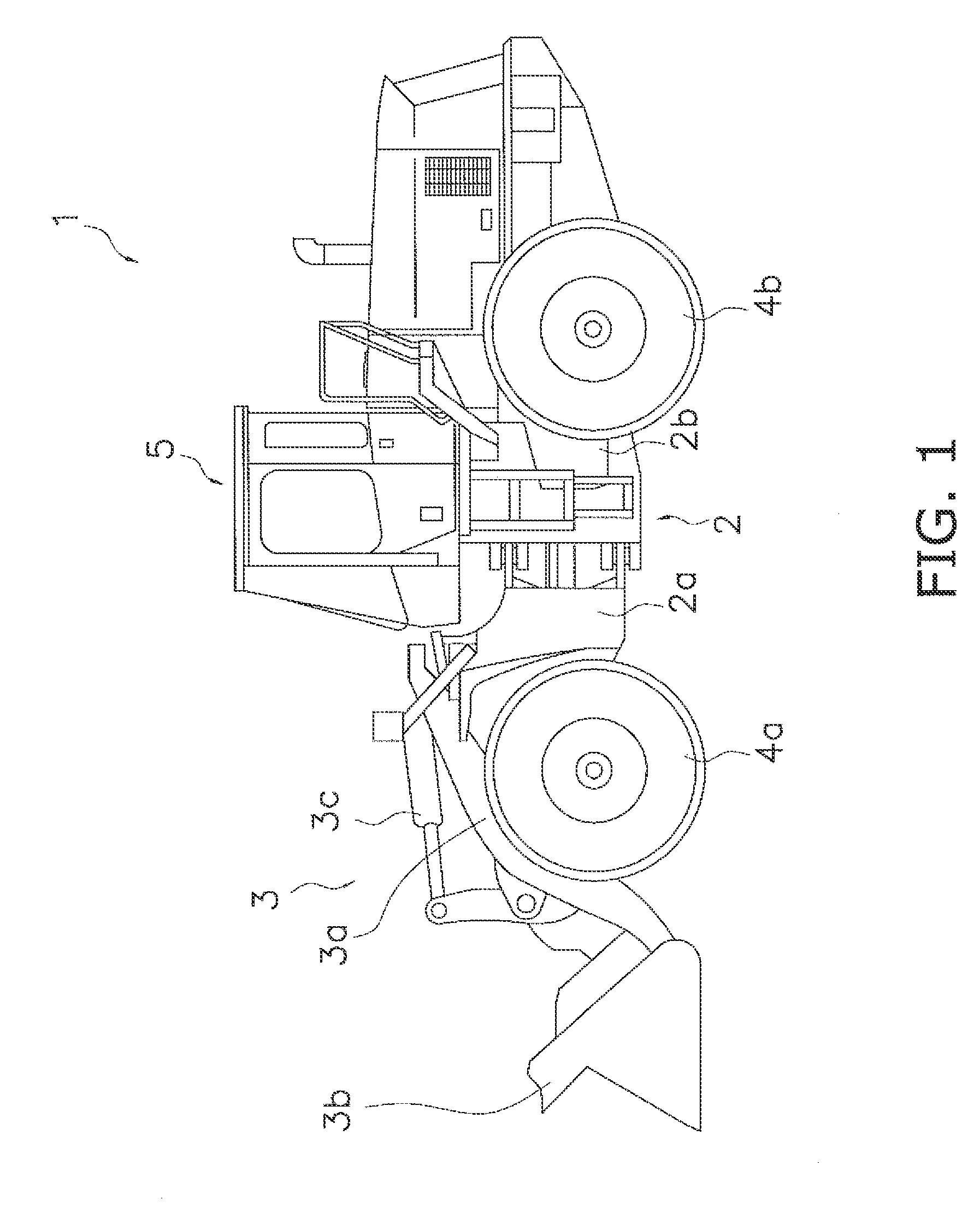
[0030]FIG. 1 is a side view of a construction vehicle 1 according to a first embodiment of the present invention. This construction vehicle 1 is a wheel loader that is capable of self-propulsion by tires 4a and 4b and can perform a desired type of work using a work machine 3. The construction vehicle 1 is provided with a body frame 2, a work machine 3, tires 4a and 4b, and an operator cab 5.

[0031]The body frame 2 has a front frame 2a frontwardly disposed and a rear frame 2b rearwardly disposed, and the front frame 2a and rear frame 2b are connected with a central part of the body frame 2 so as to be capable of swinging in the lateral direction.

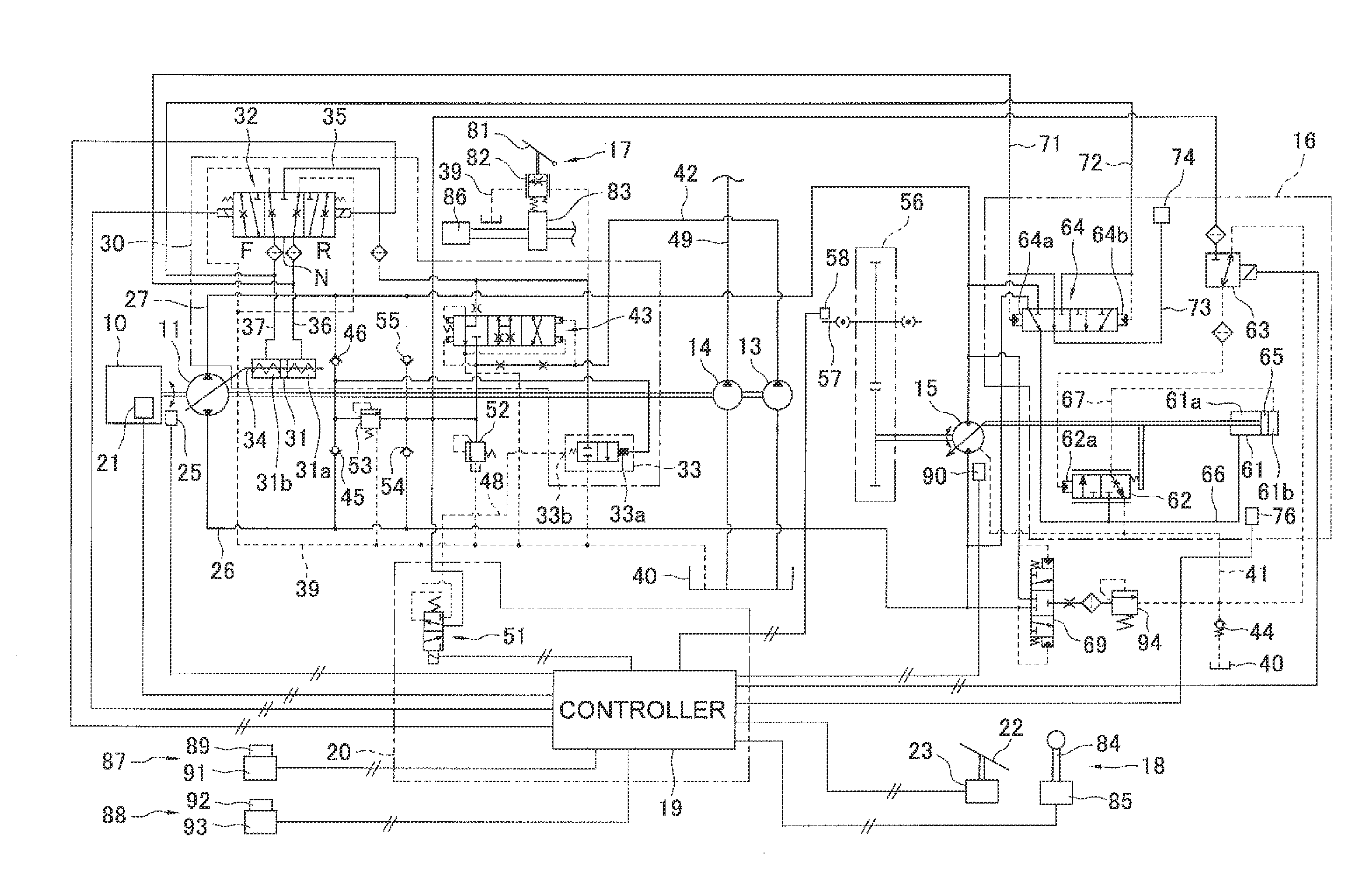
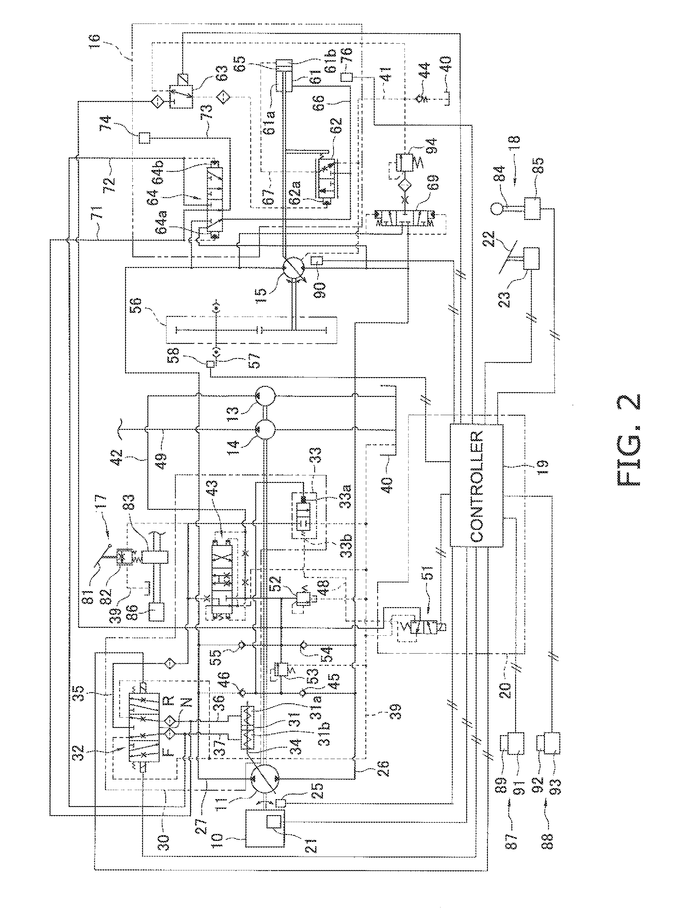
[0032]The work machine 3 and a pair of front tires 4a are attached to the front frame 2a. The work machine 3 is an apparatus driven by hydraulic fluid pumped by a second hydraulic pump 14 (see FIG. 2), and has a lift arm 3a mounted to a front part of the front frame 2a, a basket 3b attached to an end of the lift arm 3a, a ...


PUM


Abstract

In the work vehicle, a controller is configured to control a motor displacement control part via feedback control so that the driving hydraulic pressure detected by a driving hydraulic pressure detector approaches a predetermined target driving hydraulic pressure. The controller is configured to perform low temperature motor displacement limitation control, which reduces the maximum displacement of a hydraulic motor, when the temperature of the hydraulic fluid detected by the fluid temperature detector is lower than a predetermined temperature.

Description

CROSS-REFERENCE TO RELATED APPLICATIONS[0001]This application claims priority to Japanese Patent Application No. 2009-204036 filed on Sep. 3, 2009, the disclosure of which is hereby incorporated herein by reference in its entirety.TECHNICAL FIELD[0002]The present invention relates to a work vehicle.BACKGROUND ART[0003]In a work vehicle equipped with a so-called Hydrostatic transmission (HST) circuit, a hydraulic pump is driven by an engine, and hydraulic fluid discharged from the hydraulic pump is supplied to a hydraulic motor. A drive wheel is then driven by the hydraulic motor, propelling the vehicle forward.[0004]As a conventional example of a work vehicle such as that described above, a work vehicle such as that described in Japanese Laid-Open Patent Application Publication No. 2004-144254 is known in which the displacement of the hydraulic motor is electronically controlled. This work vehicle has a hydraulic motor, a cylinder, and a control valve. The cylinder has a main cylind...

Claims


Application Information

Patent Timeline
Patent Type & Authority Applications(United States)
IPC IPC(8): B60K6/08F16H61/433F16H61/431F16H61/438
CPCB60W2510/107F16H59/72F16H2059/683F16H61/431F16H61/421F15B21/045F15B2211/6343
Inventor TAKAHASHI, HIROTAKASHIINA, TORU
Owner KOMATSU LTD
Why Eureka
Try Eureka