[0027]In order to determine the effectiveness of the invention in extending the life of
hybrid tantalum capacitors, a large number of
hybrid tantalum capacitors employing
ruthenium oxide (RuO2)cathodes and sintered tantalum anodes were prepared and subjected to aging and life tests to observe the aging process and capacitor lifetime. The capacitors were tested in groups based on their rated voltages. The rated
voltage was established by forming the
oxide layer of the
anode to a particular thickness for each rated
voltage, as is known in the art. Larger thickness results in a higher
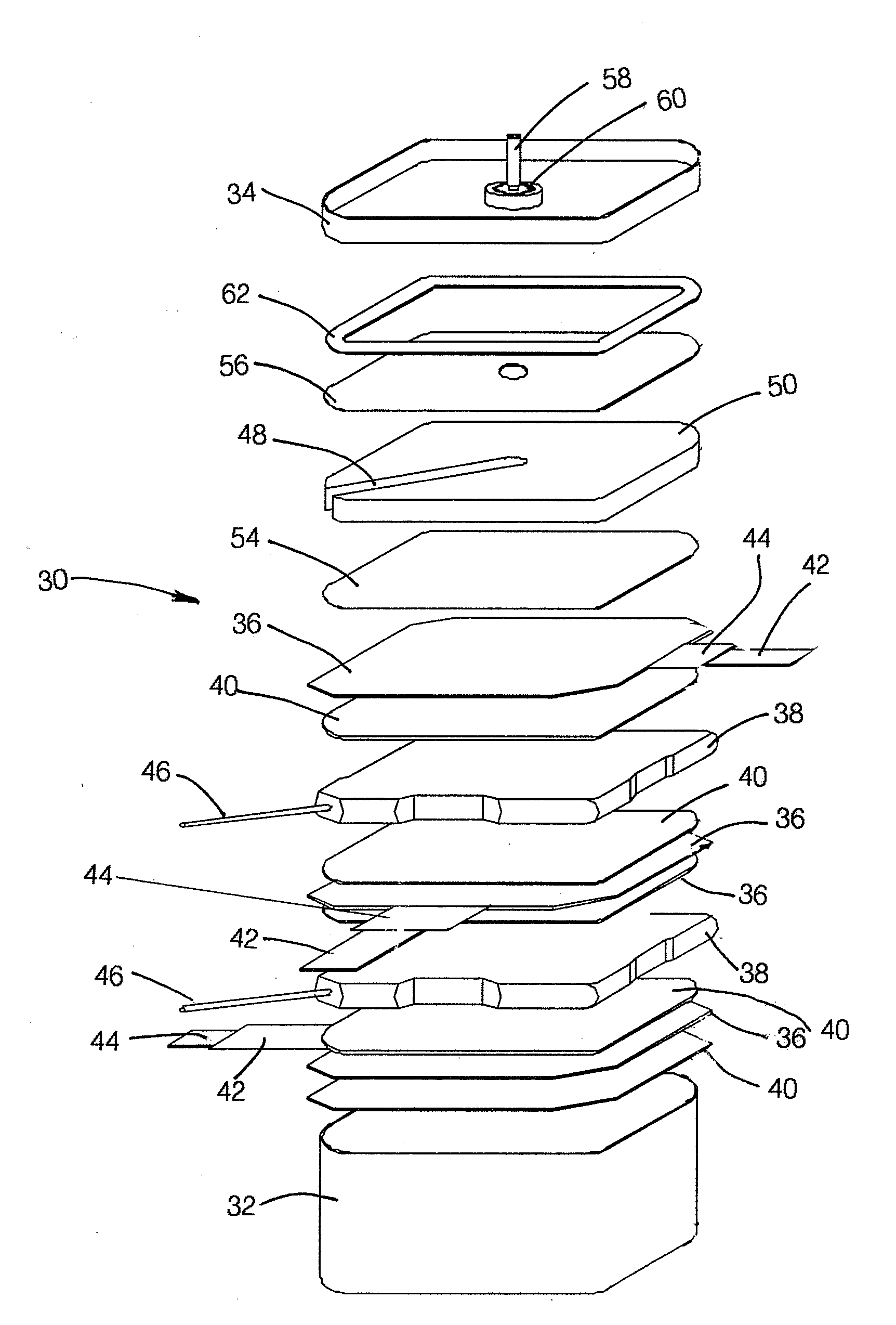
voltage rating. The tested capacitors were similar in structure to those illustrated in FIGS. 2 and 3 and had a length, sometimes referred to as the height, measured axially, from the top to the bottom of the capacitor, i.e., perpendicular to relatively planar anodes and cathodes in the configuration of FIGS. 2 and 3.
[0028]In the aging and life tests, a constant
DC voltage was applied to each capacitor. In order to accelerate aging of the capacitors being tested, the tests were carried out at elevated temperatures. In the first
aging test, a voltage equal to the rated voltage of the capacitor was applied to the capacitor, with the capacitor held at a temperature of 85° C. In order to monitor the characteristics of each capacitor, the capacitors were periodically cooled to
room temperature and the ESR,
capacitance, and swelling, namely any increase in overall height (OAH) of the capacitor, were measured. A second
aging test was performed on capacitors according to the invention in which the voltage applied to the capacitor was 60% of the rated voltage while the temperature of the capacitor was 125° C. Again, periodically, the capacitors were cooled to
room temperature and measurements of ESR,
capacitance, and OAH were made. In all tests, the rated voltages of the capacitors were treated as a parameter. For reasons not presently understood, capacitors at certain rated voltages showed better performance than capacitors with similar structures but with different rated voltages.
[0029]Leakage current may provide another indication of capacitor aging. However, leakage current was not measured in the testing that is reported here. The addition of transition
metal species to the electrolytes of the capacitors tested may actually increase the quantity of charge passed by the capacitors. However, most of that charge passes without substantial irreversible damage to the cathodes or damage to the anodes of capacitors according to the invention. Further, compared to known capacitors that include electrolyte additives intended to extend the life of those capacitors, there is a much lower rate of any irreversible damage per
coulomb of charge that is passed. The proportional relationship between the quantity of charge that is passed by a capacitor to the age of the capacitor depends upon the structure and materials of the capacitor. In capacitors according to the invention, the ratio of capacitor aging to the quantity of charge passed is decreased by a factor of at least two. This improvement is not reflected in the results of the aging and life tests that are appear in the Tables below, but represents a further important
advantage achieved in the invention.
[0030]When aging tests were carried out on a number of similar capacitors, i.e., with the same internal structure and
voltage rating, the changes in capacitance, ESR and OAH were averaged for the group of capacitors. The average changes in capacitance and ESR for various
aging test conditions are expressed in percentages in the Tables supplied below with respect to the examples of capacitors according to the invention and comparative capacitors. In the Tables, OAH is shown as an absolute change in dimension without reference to the initial axial height of the capacitor
package. The magnitude of the dimensional change, not the relative dimensional change, is a more significant characteristic in the applications made of the capacitors. Further, the
internal pressure within the capacitor causes a proportional change in height.
[0031]The life tests were a
continuation of the first aging test. Namely, in those tests the capacitors being tested were subjected to their rated voltages and were periodically cooled to
room temperature from 85° C. to measure the changes in capacitance, ESR, and OAH. The purpose of the aging tests is to show, over time, the relative changes in capacitor characteristics. The function of the life tests is to demonstrate how long a capacitor is useful, i.e., has a capacitance that does not fall below 20% of the original capacitance and / or does not suffer a doubling in the ESR. In the life tests, testing was frequently terminated before the threshold changes in capacitance and ESR that indicate failure had been reached. The tests were terminated, in some cases, to disassemble the capacitors and to detect any internal changes. In other instances, although an “end of life” hour duration is indicated in some of the Tables appearing below, there was actually no failure to perform as desired. Rather, the results are, in some instances pertaining to capacitors according to the invention, interim results. In fact, some of the life tests are continuing even as of the filing in the U.S. of this description. Some capacitors that failed, without the minimum change in capacitance or ESR that indicates failure, have failed due to mechanical failures, i.e., mechanisms that do not relate to changes in capacitance and ESR. These results suggest that the maximum possible
lifetime extension with respect to the
electrochemistry of the capacitors has been achieved in the invention. That lifetime is typically many thousands of hours as compared to a typical lifetime of about 2000 hours for a similar capacitor structure that lacks any transition
metal species electrolyte additive. Further, the comparative results show the remarkable effect of using the binary mixture of transition metal additives as compared to using only a single transition metal additive.
[0032]In addition to inclusion within the additive of two transition metal species, both having two stable oxidation states when dissolved in the electrolyte, we have found it useful to include a minor amount of a metal complexing agent in the electrolyte. More specifically,
improved performance is achieved when the electrolyte contains about 0.1%, by weight, of
thiourea, sometimes called thiocarbamide. The role of the complexing agent in extending the useful lifetime of the capacitors is not understood and no theory of its effect is proposed. Other complexing agents besides
thiourea may be effective as an electrolyte additive for increasing the lifetime of capacitors with liquid or gel electrolytes and containing a binary mixture of transition metal species.

