medical guide wire, an assembly of microcatheter and guiding catheter combined with the medical guide wire, and an assembly of ballooncatheter and guiding catheter combined with the medical guide wire

a technology of medical guide wire and guiding catheter, which is applied in the direction of catheters, heat treatment devices, furnaces, etc., can solve the problems of accumulating procedures, no technological idea has been introduced so far to utilize melting heat, etc., and achieves the reduction of lengthwise dimension, diametrically minimize the head plug, and increase the welding strength

Active Publication Date: 2012-05-17
ASAHI INTECC CO LTD
View PDF5 Cites 7 Cited by
  • Summary
  • Abstract
  • Description
  • Claims
  • Application Information

AI Technical Summary

Benefits of technology

[0050]Such is the structure that it becomes possible to increase the welding strength at the welded portion between the core wire and the helical spring body, so as to reduce the lengthwise dimension and diametrically minimize the head plug. This leads to rendering the assembly diametrically small, and imparting the microcatheter with a propelling force due to the concave-convex portion, thus realizing a minimally invasive surgery remarkably conducive to the therapeutical treatment against an obstructed portion of the vasculature.
[0051]According to other aspect of the present invention, there is provided an assembly of a balloon catheter and a guiding catheter combined with the medical guide wire. An outer diameter of the medical guide wire measures 0.228 mm-0.254 mm (0.009 inches-0.018 inches) which is inserted into the balloon catheter, an inner diameter of which measures 0.28 mm-0.90 mm, and two pairs of the medical guide wire and the balloon catheter are in...

Problems solved by technology

No technological idea has been made to utilize a melting heat produced when forming a synthetic resin layer on an outer surface of the helical spring body when the melting heat is conveyed as heat conduction to the helical spring body to improve the tensile rupture strength of the metallic wire element.
Further, no technological i...

Method used


Image

  •  medical guide wire, an assembly of microcatheter and guiding catheter combined with the medical guide wire, and an assembly of ballooncatheter and guiding catheter combined with the medical guide wire
  •  medical guide wire, an assembly of microcatheter and guiding catheter combined with the medical guide wire, and an assembly of ballooncatheter and guiding catheter combined with the medical guide wire
  •  medical guide wire, an assembly of microcatheter and guiding catheter combined with the medical guide wire, and an assembly of ballooncatheter and guiding catheter combined with the medical guide wire

Examples


first embodiment

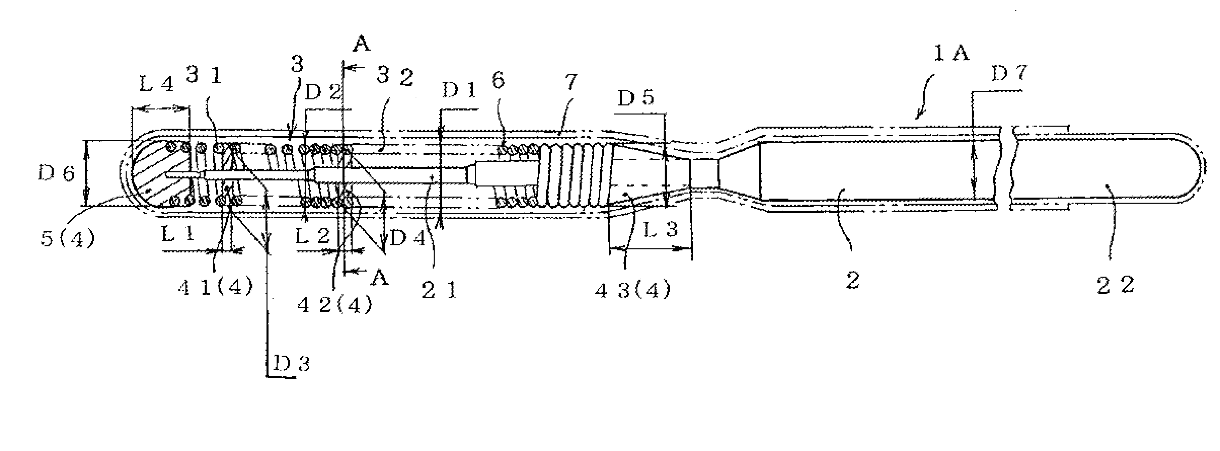
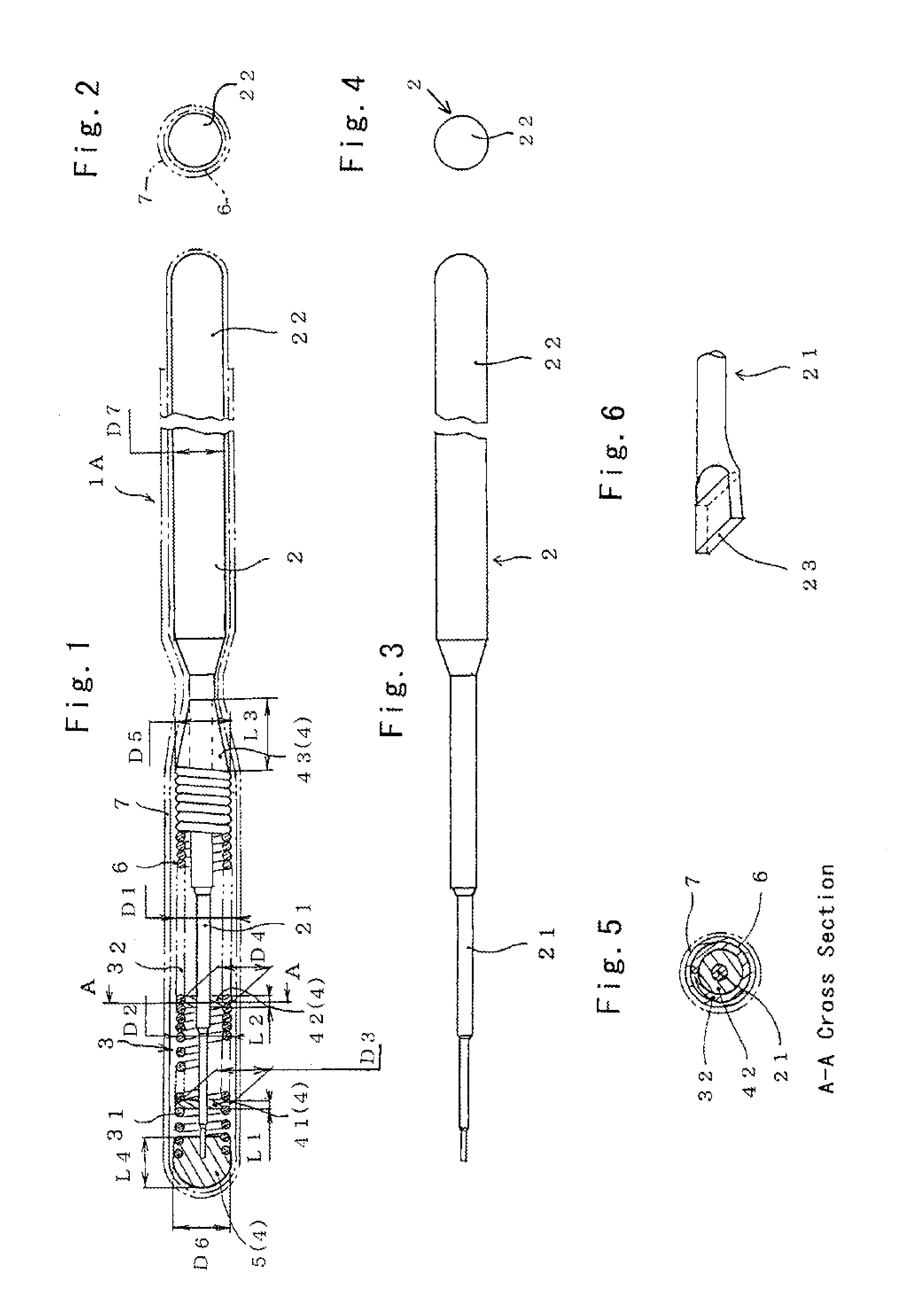
[0081]Referring to FIGS. 1 through 6 which show a medical guide wire 1A according to the invention, the guide wire 1A has a core wire 2 formed by a flexible elongate member. The core wire 2 has a distal end portion 21, around which a helical spring body 3 is coaxially placed as shown in FIGS. 1 through 5.

[0082]The helical spring body 3 has a distal end portion as a radiopaque coil 31 which is made of a metallic wire element (referred to simply as metallic wire hereinafter) such, as silver, platinum, wolfram wire or the equivalent. The helical spring body 3 has a proximal end portion as a radiotransparent coil 32 which is formed by winding a stainless steel wire around the core wire 2. The metallic wire of the radiopaque coil 31 and the stainless steel wire of the radiotransparent coil 32 have a diameter within a range of 0.050 mm-0.095 mm.

[0083]At a distal end portion 21 of the core wire 2, an intermediate front weld portion 41, an intermediate rear weld portion 42 and a rear side w...

eighth embodiment

[0099]As described hereinafter in detail at sixth to eighth embodiment of the invention (FIGS. 19-23), the present invention includes bonded features when the helical spring body 3 and an inner helical spring body 33 are mutually bonded, and the spring bodies 3, 33 are bonded to the distal end portion 21 of the core wire 2 so as to form a double-layered construction in which the inner helical spring body 33 is concentrically placed between the helical spring body 3 and the distal end portion 21 of the core wire 2. The inner helical spring body 33 is formed from a radiotransparent coil which measures 0.185 mm (0.357 mm or less) in diameter (D11).

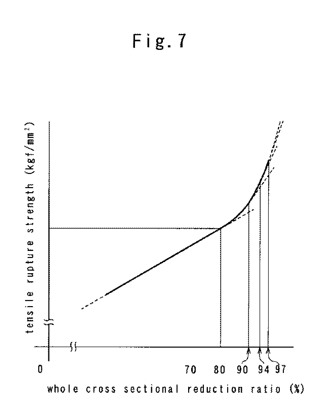
[0100]In Tables 1, 2 which shows the metallic wire employed to the radiotransparent coil 32 and the inner helical spring body 33, the austenitic stainless steel wire (0.3 mm in diameter, 70 kgf / mm2 in tensile rupture strength) is treated with the solid-solution procedure as a first metallic wire 1e, and primarily drawn to have the whole cross...

second embodiment

[0206]FIGS. 10 and 11 show the invention in which a medical guide wire 1B has the radiotransparent coil 32 formed by the metallic wires 1a-1f.

[0207]Between an outer surface of the core wire 2 and an inner surface of the helical spring body 3, there are provided a plurality of intermediate front weld portions 411-420 arranged lengthwise at regular intervals (C: e.g., 10 mm) along the core wire 2 beyond a portion proximally distanced by a predetermined length (D: e.g., 50 mm) from a distal extremity of the head plug 5. Although the number of the intermediate front weld portions 411-420 is counted as ten to extend by 90 mm along the lengthwise direction, the intermediate front weld portions 414-419 are omitted for the sake of convenience.

[0208]By forming the intermediate front weld portions 411-420 with the use of the welding member 4, it is possible to heat treat the radiotransparent coil 32 in low temperature without using the furnace, so as to improve the tensile rupture strength o...


PUM

PropertyMeasurementUnit
Temperatureaaaaaaaaaa

Abstract

In a medical guide wire 1, a helical spring body 3 is made of austenitic stainless steel wire treated with a solid-solution procedure, and tightly drawn with a whole cross sectional reduction ratio as 90%-99.5%. A metallic wire element of the helical spring body 3 is heat treated at low temperature within a range in which a tensile rupture strength of the helical spring body 3 rapidly increases by partly or totally making use of a conductive heat generated when a core wire 2 and the helical spring body 3 are in part bonded by means of a welding member 4. This makes it possible to improve a mechanical strength property, especially a fatigue-resistant property against a repetitive bending action of the helical spring body 3.

Description

BACKGROUND OF THE INVENTION[0001]1. Field of the Invention[0002]The present invention relates to a medical guide wire in which a metallic wire element of a helical spring body is improved at its mechanical strength properties by bonding a core wire to the helical spring body by means of a welding member.[0003]2. Description of Related Art[0004]In general, a medical guide wire (referred to simply as a guide wire) is thinned so that the guide wire is inserted into a somatic vasculature. With the thinned wire in mind, it is necessary to impart mechanical requirements to the guide wire with safety measures secured for a human body. For this purpose, various types of contrivances have been introduced.[0005]In Japanese Pre-grant Patent Publication No. 4-25024 (referred to as a first reference hereinafter), the first reference discloses a medical guide wire in which a helical spring body has a radiotransparent coil and a radiopaque coil each connected at a distal end portion of a core wire...

Claims


Application Information

Patent Timeline
IPC IPC(8): A61M25/09A61M25/10A61M25/098A61F2/958
CPCA61M25/09A61M2025/09083A61M2025/09091A61M2025/09108A61M2025/09133C21D9/52B23K35/004C21D8/06C21D8/065C21D9/02A61M2025/09175
Inventor KATO, TOMIHISA
Owner ASAHI INTECC CO LTD
Why Eureka
Try Eureka