Scratch Resistance Test Methods and Apparatus

a test method and scratch resistance technology, applied in the direction of measuring devices, investigating material hardness, instruments, etc., can solve problems such as mar type damage, damage commonly found on paint coats and dashboard surfaces, and testing parameters that do not accurately simulate damage modes

Inactive Publication Date: 2012-05-03
HONDA MOTOR CO LTD
View PDF1 Cites 8 Cited by
  • Summary
  • Abstract
  • Description
  • Claims
  • Application Information

AI Technical Summary

Benefits of technology

[0014]As will be appreciated by those skilled in the art, the tool holder(s) may be configured for receiving a wide variety of tools including, for example, shovels, rakes, concrete block and aggregate mixtures, that may be used to simulate the types of damage modes anticipated for the particular MUT. Similarly, the apparatus may incorporate additional elements such as weights, springs or other biasing means for controlling the force with which the tool is forced against the MUT to provide a reasonable “real-world” simulation. The apparatus may, for example, allow for manual translation of the tool relative to the MUT or, in other embodiments, may incorporate motive elements including, for example, hydraulic, pneumatic, belt-drive or direct-drive systems for initiating and controlling the motion of the tool relative to the MUT.

Problems solved by technology

Examples of mar type damage include the damage commonly found on paint coats and dashboard surfaces that have suffered minor damage through contact with small objects such as stones, sticks, car doors or keys that have impacted the surface under evaluation.
As a result, these devices and methods tend to utilize testing parameters that do not accurately simulate the damage modes that would be expected during the actual use of the materials and components.
For example, some conventional testing methods and apparatus means may yield inconsistent and irreproducible data and results when they are applied to a component under test.
For example, for parts that are heavily textured, the small stylus used in some conventional testing devices may be prone to “skip” or “bounce” during testing, thereby contributing to inconsistent testing results.
In such instances, the inconsistent and irreproducible data and results complicate the ability of the engineers to produce a valid comparison between competing designs or compositions that would be helpful in guiding further development efforts.
In many instances, conventional bench testing is limited in its ability to simulate with a reasonable degree of confidence, the impact and contact conditions that would be reasonably expected to be endured by the materials / components under test during their normal service life.
Further, many conventional devices may not allow for variable load or variable scratch speed testing during the completion of a single test.
Still further, some conventional scratch testing devices may be unable to measure and capture quantitative data (e.g., load, scratch speed, scratch depth, etc.) during the actual surface test, producing instead a scratched and / or marred sample that is subjected to separate, and generally only qualitative, study.
Without gathering quantitative data during testing, it may not be possible to verify that the intended load conditions and scratch speed actually occurred during testing, thereby rendering the test data less useful for comparison and decision making.
As will be appreciated, pins having 1.0 mm or 7.0 mm diameter hemispherical contact surfaces, while perhaps delivering repeatable results, do not reflect the sort of damage modes that would be expected to affect polymeric components integrated into vehicles, particularly those incorporated to form exterior surfaces and, in particular, the load-bearing surfaces of pickup cargo beds.

Method used


Image

  • Scratch Resistance Test Methods and Apparatus
  • Scratch Resistance Test Methods and Apparatus
  • Scratch Resistance Test Methods and Apparatus

Examples


Embodiment Construction

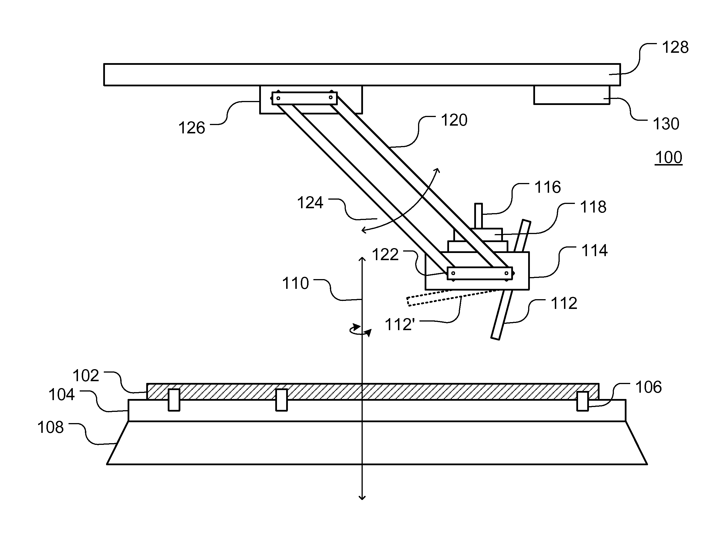
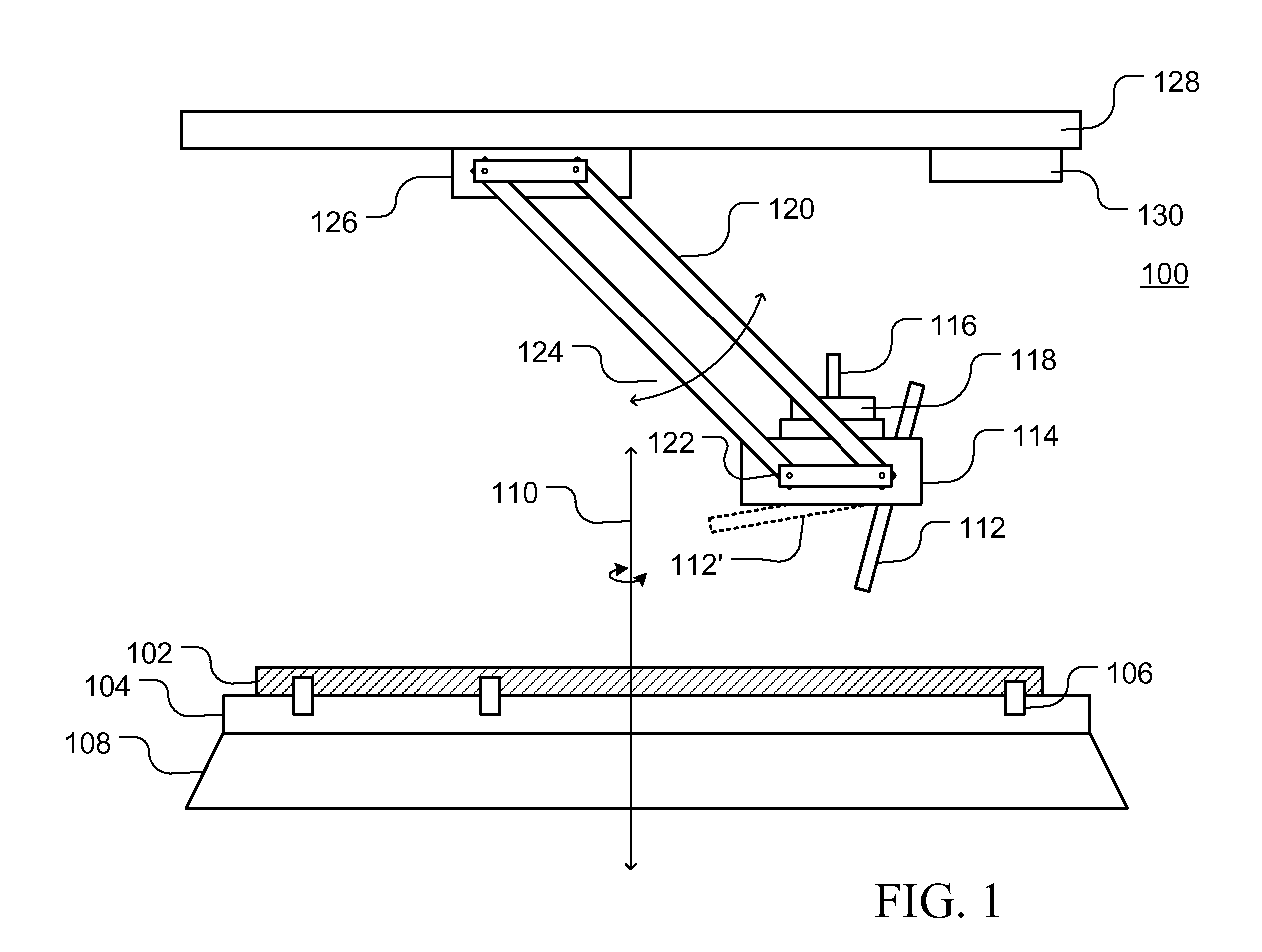
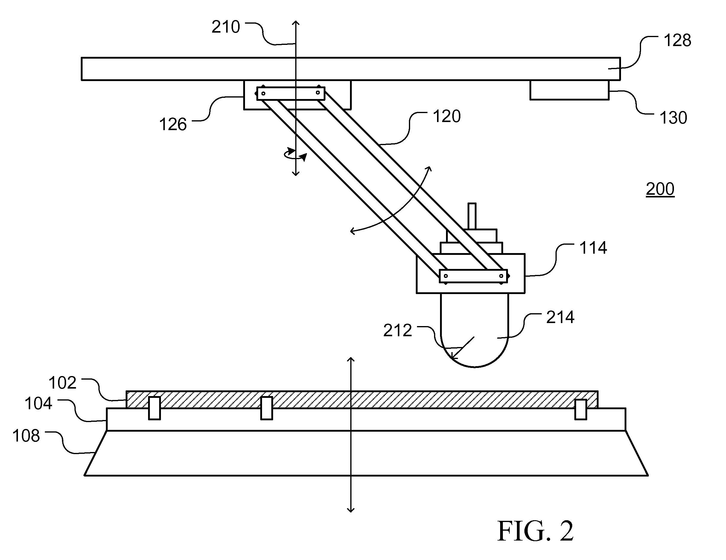
[0028]As will be appreciated by those in the art, polymeric materials have been incorporated into a wide range of products including, for example, vehicles, as both interior and exterior components. In light of the continued interest in reducing the weight, cost and assembly associated with a particular vehicle, the use of exterior polymeric panels and components that may be manufactured from a variety of materials including, for example, a variety of rigid plastics and extra rigid plastics may be used for external applications that would typically be expected to endure substantial contact events over the life of the part. Examples of such materials include, for example, acrylonitrile butadiene styrene (ABS), polycarbonate (PC), polypropylene (PP), sheet molded compound (SMC), fiberglass reinforced polyester (FRP), polycarbonate / acrylonitrile butadiene styrene (PC / ABS) compositions and Honda polymer alloy (HPA). The materials may be utilized in manufacturing a wide variety of automo...


PUM


Abstract

The apparatus and methods disclosed may be utilized for the scratch / mar testing of various materials and components that provide improved correlation between the simulated damage modes and those reasonably expected to be encountered by the final components. The apparatus includes both a fixture configured for receiving and holding the material under test (MUT) and a tool holder that is arranged and configured for supporting and holding a variety of test tools in one or more orientations relative to the MUT. The tool holder and / or the fixture are, in turn, supported by one or more assemblies arranged and configured for bringing the tool into contact with the MUT and providing for movement of the tool relative to the MUT. The apparatus is then used for collecting data from a series of tests that can be used to compare the performance of different MUT compositions and configurations.

Description

TECHNICAL FIELD[0001]The present disclosure relates to abrasion and durability test apparatus and test methods for simulating typical use / abuse modes for evaluating the wear and durability characteristics of various types of materials, including, for example, polymeric sheet molding compounds (“SMC”). More particularly, the present disclosure relates to a collection of wear and durability test apparatus and methods that can perform controlled and repeatable abrasion and durability tests during the development of materials and components that will that provide more reliable data during development projects.BACKGROUND[0002]In light of the increasing use of polymeric materials in vehicle manufacture, surface testing and analysis of such materials and components manufactured from such materials, is a current area of interest in the fields of material science and mechanics. The increased interest in evaluating scratch and / or mar resistance of polymers stems from the increasing use of pol...

Claims


Application Information

Patent Timeline
IPC IPC(8): G01N3/56
CPCG01N3/56G01N3/46
Inventor RYAN, JAMESHUTTER, ALEXANDER
Owner HONDA MOTOR CO LTD
Why Eureka
Try Eureka