
Heat conductivity coefficient and heat diffusivity transient body heat source measuring method

A technology of thermal conductivity and thermal diffusivity, which is applied in the field of material thermophysical parameter measurement, can solve the problems of large volume effect thermophysical parameter measurement error, steady-state method is easily affected by edge effects, and large device volume. Short, avoid edge effects, small size effect

Active Publication Date: 2019-01-04
HARBIN INST OF TECH
View PDF5 Cites 10 Cited by
  • Summary
  • Abstract
  • Description
  • Claims
  • Application Information

AI Technical Summary

Problems solved by technology

[0005] The purpose of the present invention is to solve the problem that the existing steady-state method is easily affected by the edge effect, so it is necessary to increase the thermal protection structure, which leads to its complex structure, large device volume, and unsteady-state thermal conductivity measurement methods such as hot wire method and plane In the measurement models such as the heat source method, the volume effect of the heating probe and the large error in the measurement of the thermal physical parameters caused by the shape of the probe are not accurately considered, so a transient body heat source measurement method of thermal conductivity and thermal diffusivity is proposed

Method used


Image

  • Heat conductivity coefficient and heat diffusivity transient body heat source measuring method
  • Heat conductivity coefficient and heat diffusivity transient body heat source measuring method
  • Heat conductivity coefficient and heat diffusivity transient body heat source measuring method

Examples


specific Embodiment approach

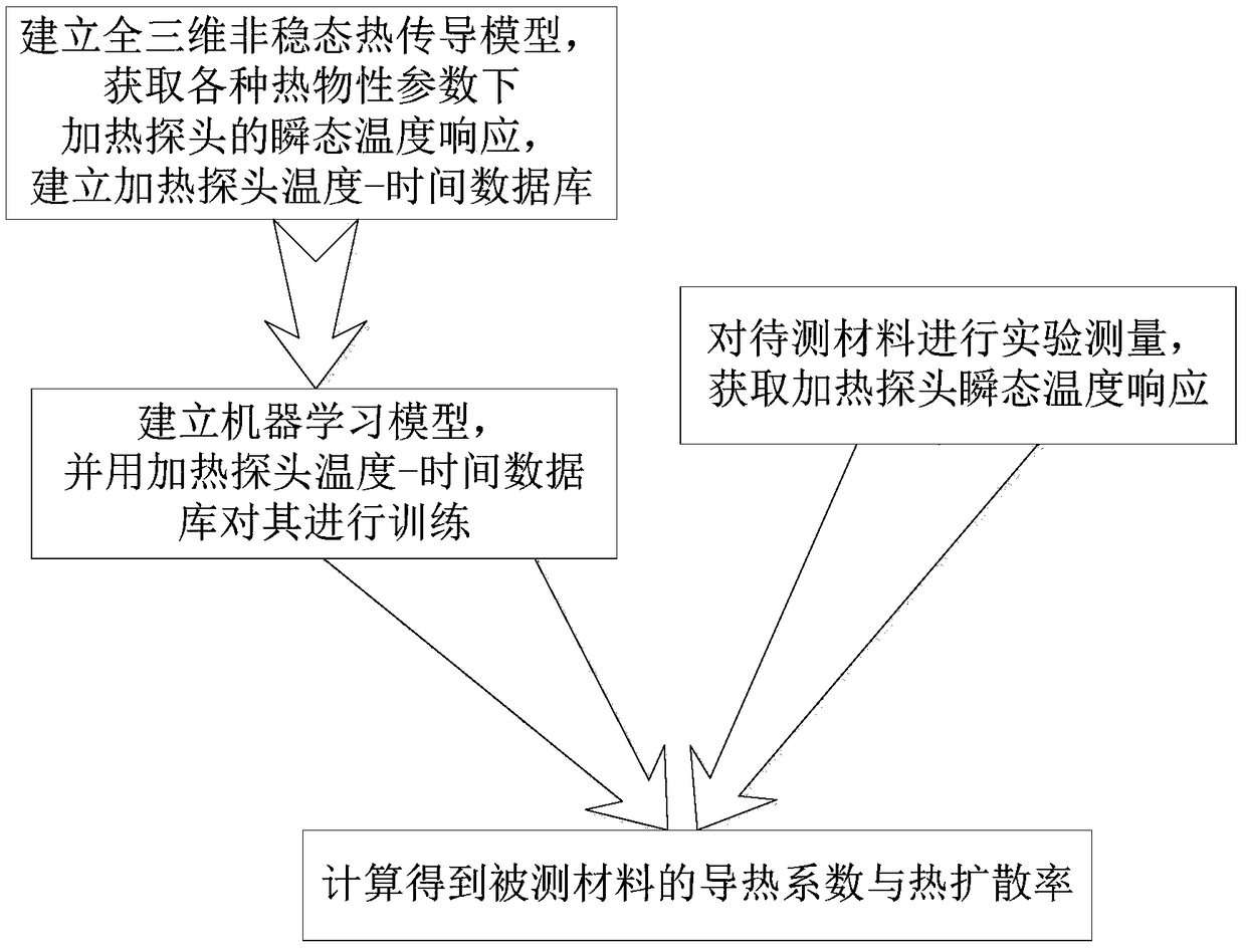
[0049] Specific implementation method: combined image 3 To illustrate this embodiment, the specific process of a transient body heat source measurement method for thermal conductivity and thermal diffusivity in this embodiment is as follows:

[0050] Step 1: Establish a three-dimensional heat transfer model for measuring thermal conductivity; program and calculate the transient average temperature rise of the heating probe under different thermal diffusivity and thermal conductivity based on the three-dimensional heat transfer model, and establish the dimensionless average of the heating probe under different dimensionless thermal physical parameters Excess temperature - dimensionless time database;

[0051] Step 2: Based on the dimensionless average excess temperature-dimensionless time database of the heating probe under different dimensionless thermophysical parameters established in step 1, establish a machine learning model of the thermophysical parameters of the measure...

specific Embodiment approach 2

[0054] Specific embodiment 2: The difference between this embodiment and specific embodiment 1 is: in the step 1, a three-dimensional heat transfer model for measuring thermal conductivity is established; State average temperature rise, and establish the dimensionless average excess temperature-dimensionless time database of heating probes under different dimensionless thermophysical parameters; the specific process is:

[0055] Step 11: Establish a three-dimensional simplified heat transfer model of the experimental device for measuring thermal conductivity. Different from the traditional Hot Disk method, this model fully considers the thickness of the heating probe and the contact thermal resistance between the heating probe and the material to be tested.

[0056] Establish a three-dimensional simplified heat transfer model for measuring thermal conductivity;

[0057] Step 1 and 2: Analyze the heat conduction process of the heat transfer model, and establish the heat conduct...

specific Embodiment approach 3

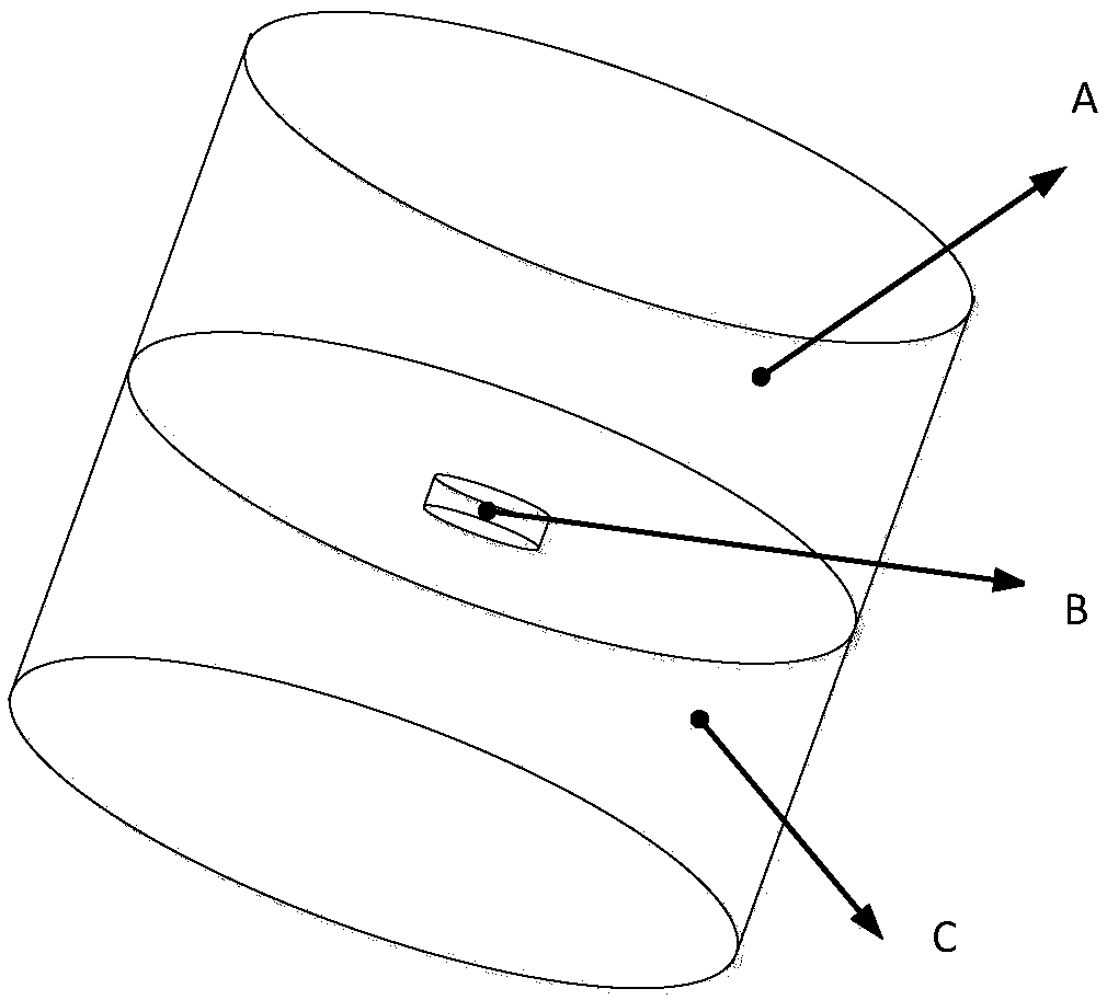
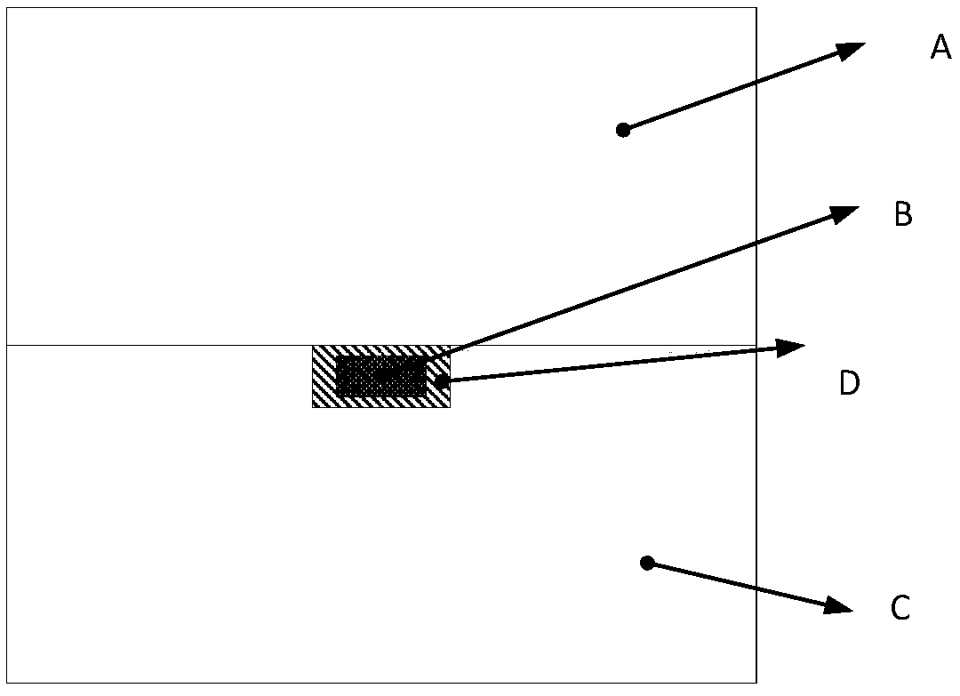
[0094] Specific embodiment three: the difference between this embodiment and specific embodiment one or two is: the full three-dimensional simplified model of the experimental device for measuring thermal conductivity is established in the step one by one, which is different from the traditional Hot Disk method, and the full consideration of this model is The thickness of the heating probe and the thermal contact resistance between the heating probe and the material to be tested; combined figure 1 , figure 2 illustrate;

[0095] Establish a three-dimensional simplified heat transfer model for measuring thermal conductivity, the specific process is as follows:

[0096] The heat transfer model includes three parts: the material to be tested, the base and the heating probe;

[0097] The material to be tested is made into a cylinder;

[0098] The base material is a cylinder with the same size as the material to be tested, and the base material is polycrystalline mullite fiber,...


PUM

PropertyMeasurementUnit
Thermal conductivityaaaaaaaaaa
Thermal diffusivityaaaaaaaaaa
Thermal conductivityaaaaaaaaaa

Abstract

The invention relates to a heat conductivity coefficient and heat diffusivity transient body heat source measuring method, and aims to solve the problems that an existing steady-state method needs addition of a heat protection structure, consequently, a device is complicated in structure and large in size, the shape and the volume effect of a heating probe cannot be accurately considered in a measuring model of non-steady state methods such as a planar heat source method, and measuring errors are large. The measuring method particularly includes the steps: first, building an excess temperature-time database of the heating probe with different thermophysical parameters; second, building a machine learning model of the thermophysical parameters and transient temperature rise of the heating probe based on the database built in the first step; third, acquiring change data of temperature rise of the heating probe with the passage of time by experimental measurement; fourth, calculating theheat conductivity coefficient and the heat diffusivity of a measured material according to the machine learning model built in the second step and the change data of temperature rise of the heating probe with the passage of time. The measuring method is used for the field of thermophysical parameter measurement of the material.

Description

technical field [0001] The invention belongs to the field of measuring thermophysical parameters of materials, and relates to a method for measuring a transient body heat source of thermal conductivity and thermal diffusivity. Background technique [0002] As important thermophysical parameters, thermal conductivity and thermal diffusivity are important indicators reflecting the heat transfer performance of materials, and provide an important basis for the design of heat transfer in various industries. With the continuous discovery of new materials and the continuous expansion of the use conditions of materials, it is of great significance to accurately measure the thermal conductivity and thermal diffusivity of materials. At present, there are two kinds of methods for experimentally measuring the thermal conductivity of materials, namely steady-state method and unsteady-state method. [0003] Steady-state methods are mostly based on the one-dimensional Fourier heat conduct...

Claims


Application Information

Patent Timeline
IPC IPC(8): G01N25/20
CPCG01N25/20
Inventor 赵军明王壮刘林华
Owner HARBIN INST OF TECH
Learn More