
Systems and methods of measuring residual stress in metallic materials

a residual stress and metal technology, applied in the direction of force measurement, material analysis using wave/particle radiation, instruments, etc., can solve the problems of inability to accurately and meaningfully measure residual stress, limited measurement by diffraction methods alone, and complicated theoretical calculations of residual stress. , to achieve the effect of reducing exposure to corrosion and accurate and meaningful measurement of residual stress

Active Publication Date: 2006-11-23
THE BOEING CO
View PDF19 Cites 8 Cited by
  • Summary
  • Abstract
  • Description
  • Claims
  • Application Information

AI Technical Summary

Benefits of technology

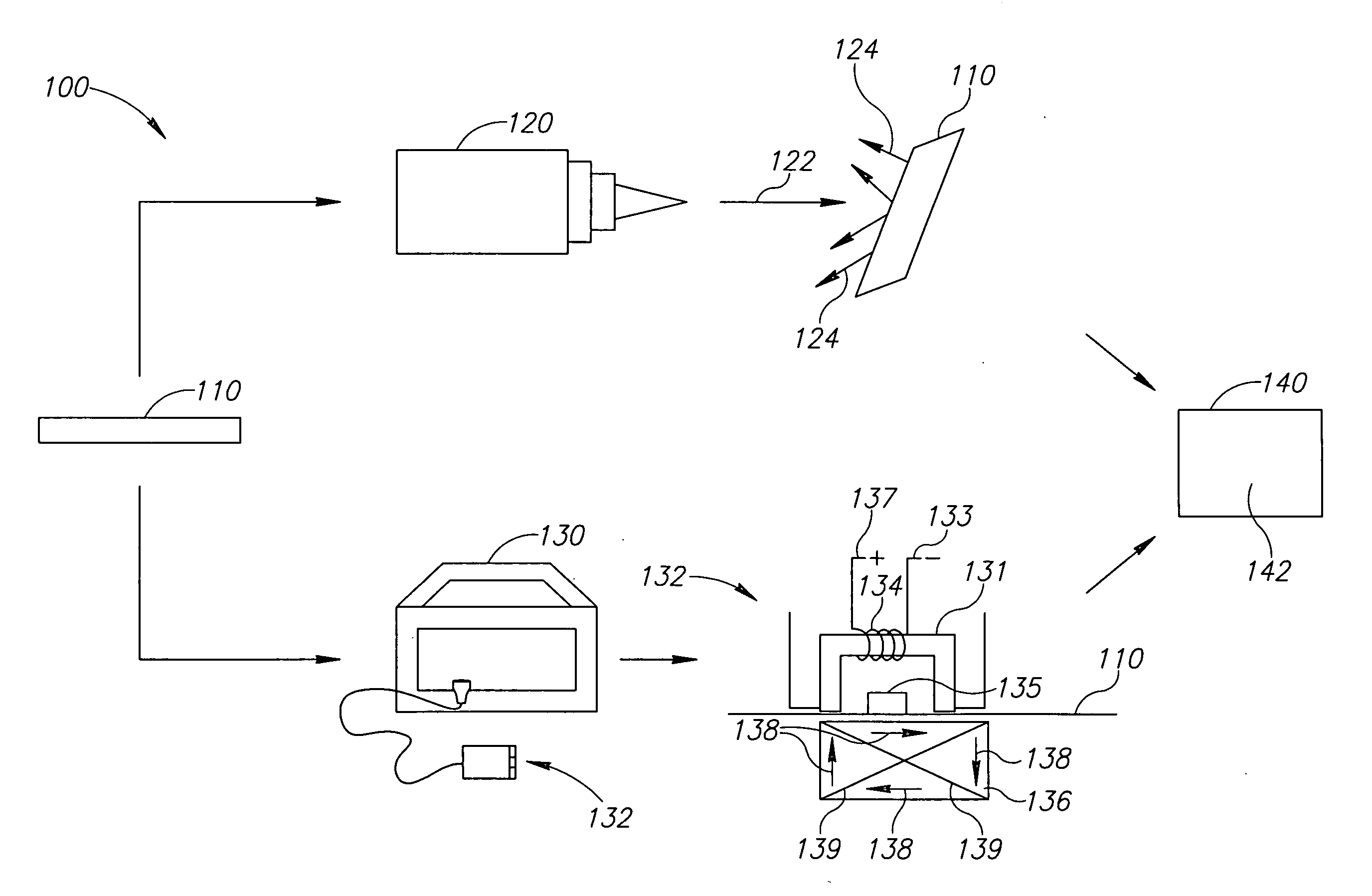
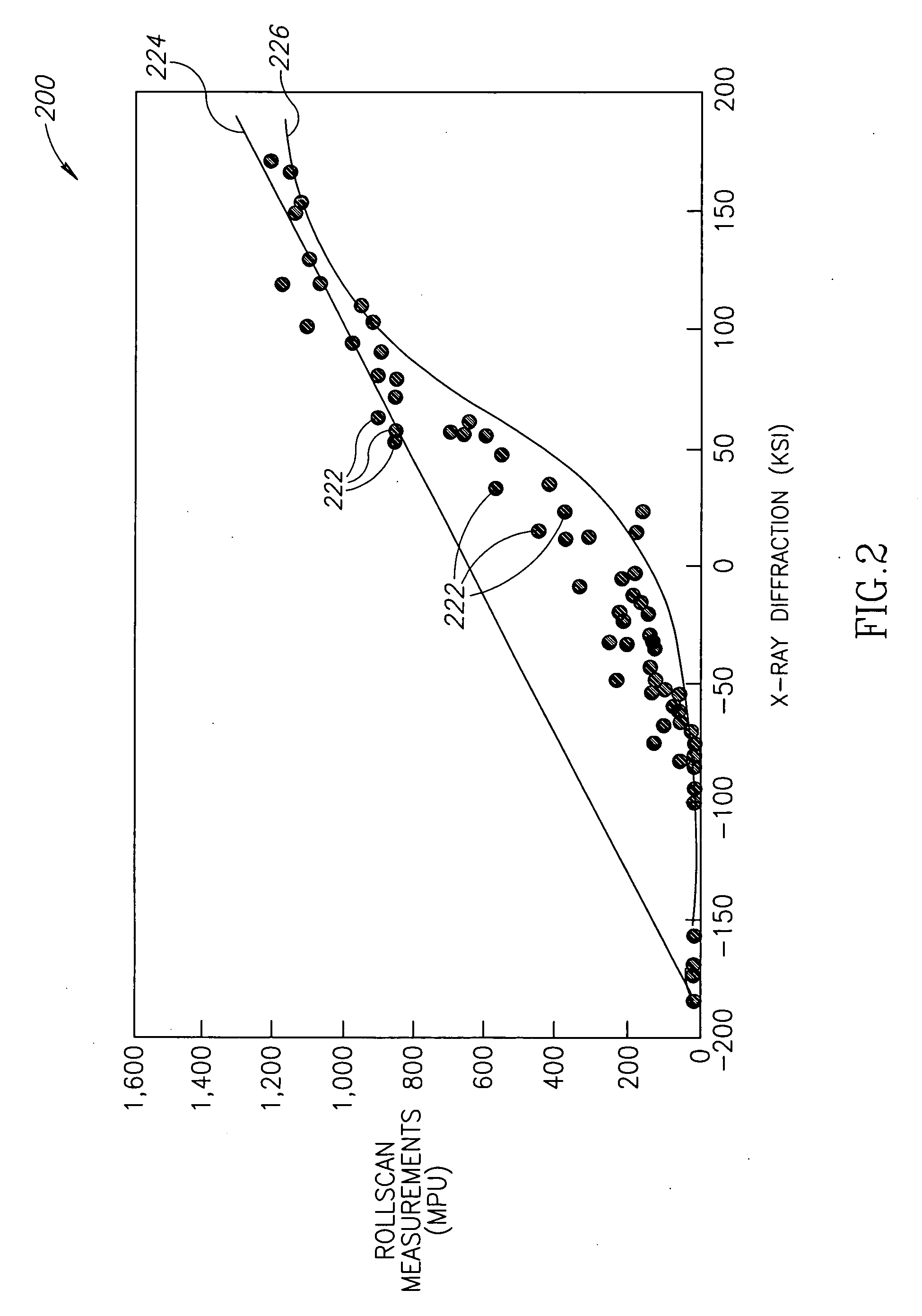
The present invention provides systems and methods for accurately measuring residual stress in metallic materials, including plated and coated materials. This helps to significantly reduce exposure to corrosion. The method involves inducing magnetoelastic interactions within the stressed material, sensing the interactions, and determining the residual stress by comparing the interactions with an empirical database developed from measurements from multiple specimens.

Problems solved by technology

Because the measurements are indirect representations of displacement at the surface, the residual stress calculations are theoretically complex and tedious, and can only be performed on nonplated and noncoated parts.
Diffraction methods alone may be limited to measuring across a large number of positions on the material to obtain unrevealing information, particularly where the material being tested has been used in the field where corrosion and other environmental use conditions can cause highly localized variations in the strength characteristics being determined.

Method used


Image

  • Systems and methods of measuring residual stress in metallic materials
  • Systems and methods of measuring residual stress in metallic materials
  • Systems and methods of measuring residual stress in metallic materials

Examples


Embodiment Construction

[0013] The present invention relates to systems and methods of measuring residual stress in metallic materials. Many specific details of certain embodiments of the invention are set forth in the following description and in FIGS. 1-4 to provide a thorough understanding of such embodiments. One skilled in the art, however, will understand that the present invention may have additional embodiments, or that the present invention may be practiced without one or more of the details described in the following description.

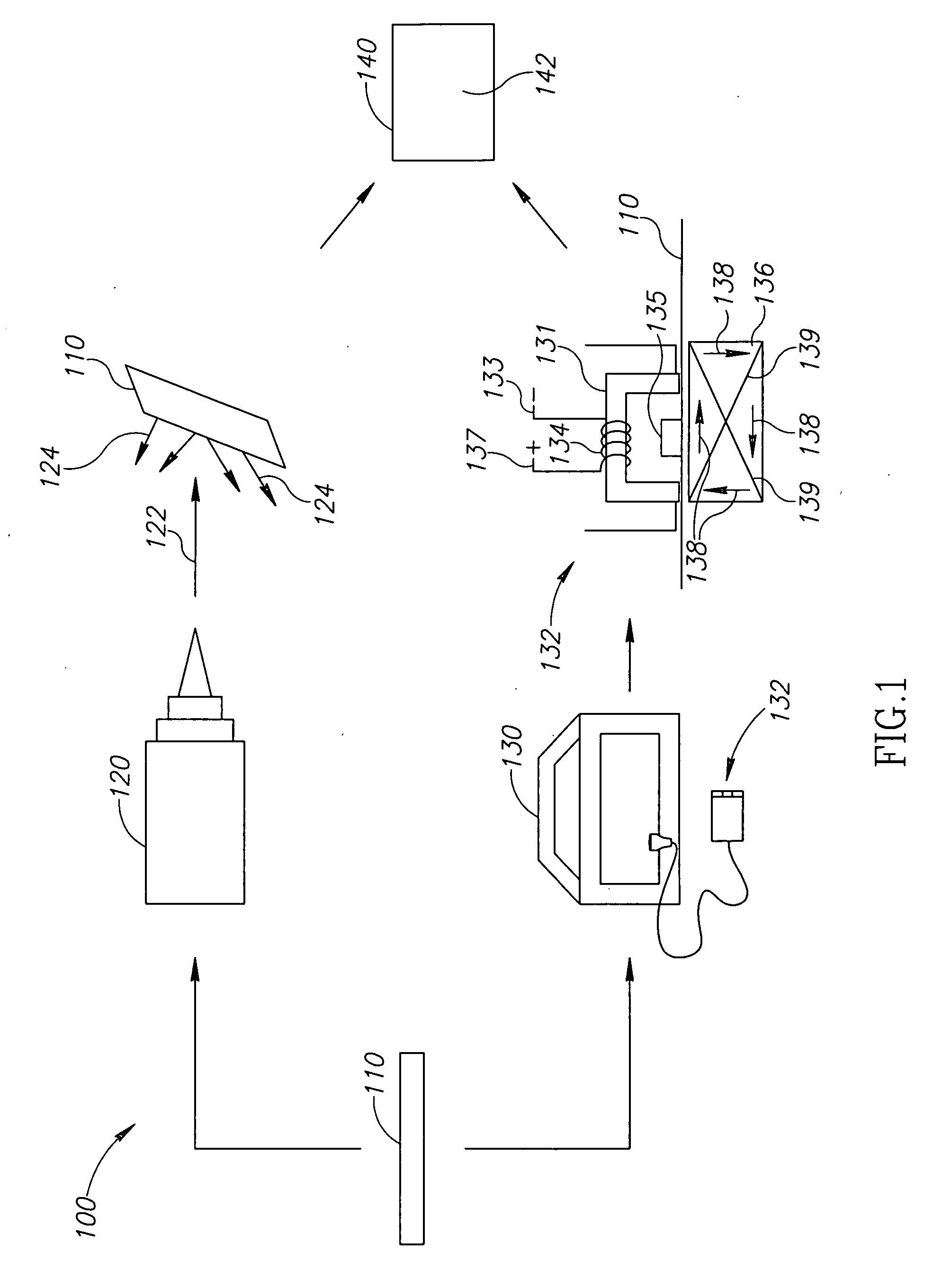
[0014]FIG. 1 is a schematic view of a system 100 for measuring residual stress in a stressed material 110 according to an embodiment of the present invention. In one aspect, the system 100 includes a radiation device 120, an electromagnetic assembly 130, and a data reduction system 140 for combining the measurements of the radiation device 120 and the electromagnetic assembly 130. The radiation device 120 directs radiation 122 onto the stressed material 110 and detects t...


PUM


Abstract

Systems and methods of measuring residual stress are disclosed. In one embodiment, a method of measuring residual stress in a material under test includes directing radiation onto a stressed material and detecting the resulting diffraction peaks to measure known residual stress of a control specimen, inducing and sensing magnetoelastic interactions onto the control specimen, developing an empirical database of the diffraction and magnetoelastic interaction measurements of the control specimen, inducing and measuring magnetoelastic interactions on a material under test, and correlating the empirical database to the magnetoelastic interaction outputs from the material under test.

Description

GOVERNMENT LICENSE RIGHTS [0001] This invention was made with Government support under U.S. Government contract N00019-02-C-3044 awarded by United States Navy. The Government has certain rights in this invention.FIELD OF THE INVENTION [0002] The present disclosure relates generally to systems and methods of measuring residual stress and, more specifically, to measuring residual stress in metallic materials. BACKGROUND OF THE INVENTION [0003] The different magnitudes of stress throughout an object are known as residual stress. The name comes primarily from the fact that residual stress is the stress remaining within an object as a result of service induced overloads, forming, shaping or other processing that changes the internal residual stress of an object. Objects are generally formed by exposure to a change in energy, heat, or an application of pressure. Whenever an object is exposed to such a change or local deformation occurs, residual stresses may change. This change in residua...

Claims


Application Information

Patent Timeline
Patent Type & Authority Applications(United States)
IPC IPC(8): G01B7/16
CPCG01N3/068G01N23/203G01N2203/0069G01N2203/005G01N2203/0005
Inventor SAGUTO, GREGORY P.
Owner THE BOEING CO
Learn More