
Flux controller for induction motor

a technology of induction motor and controller, which is applied in the direction of motor/generator/converter stopper, dynamo-electric converter control, dynamo-electric gear control, etc., can solve the problem that the low-speed region of the motor is reduced, the low-speed region of the flux estimation performance is deteriorated, and the low-speed region of the sensorless vector control method is not sufficient to compare with the high-speed region. achieve the effect of maintaining th

Active Publication Date: 2012-04-19
LSIS CO LTD
View PDF3 Cites 19 Cited by
  • Summary
  • Abstract
  • Description
  • Claims
  • Application Information

AI Technical Summary

Benefits of technology

[0042]Accordingly, an object of the present invention is to provide a flux controller for a motor, which is mounted on an inverter-motor drive system for driving the induction motor having no velocity or position sensor at variable velocity, thus maintaining sensorless flux estimation performance even in a low velocity region where a magnitude of voltage is small.
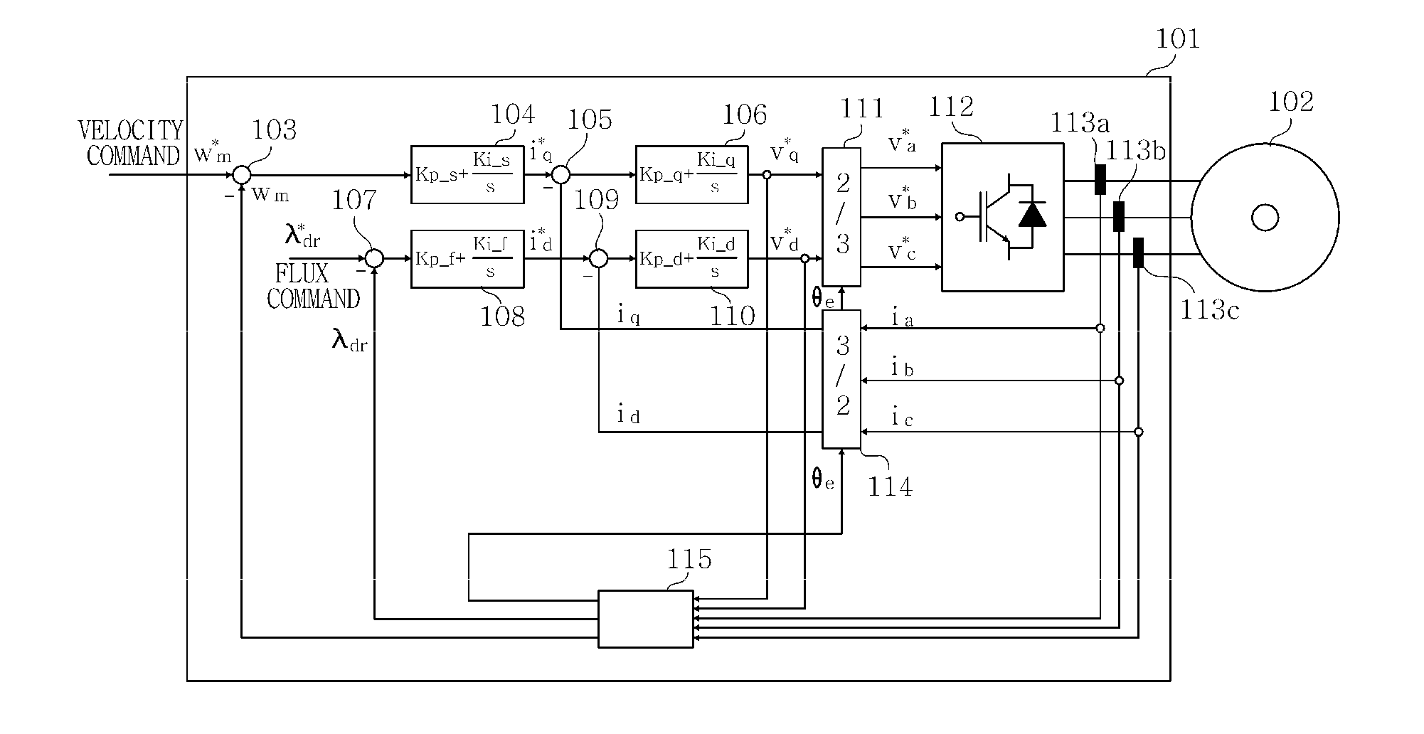
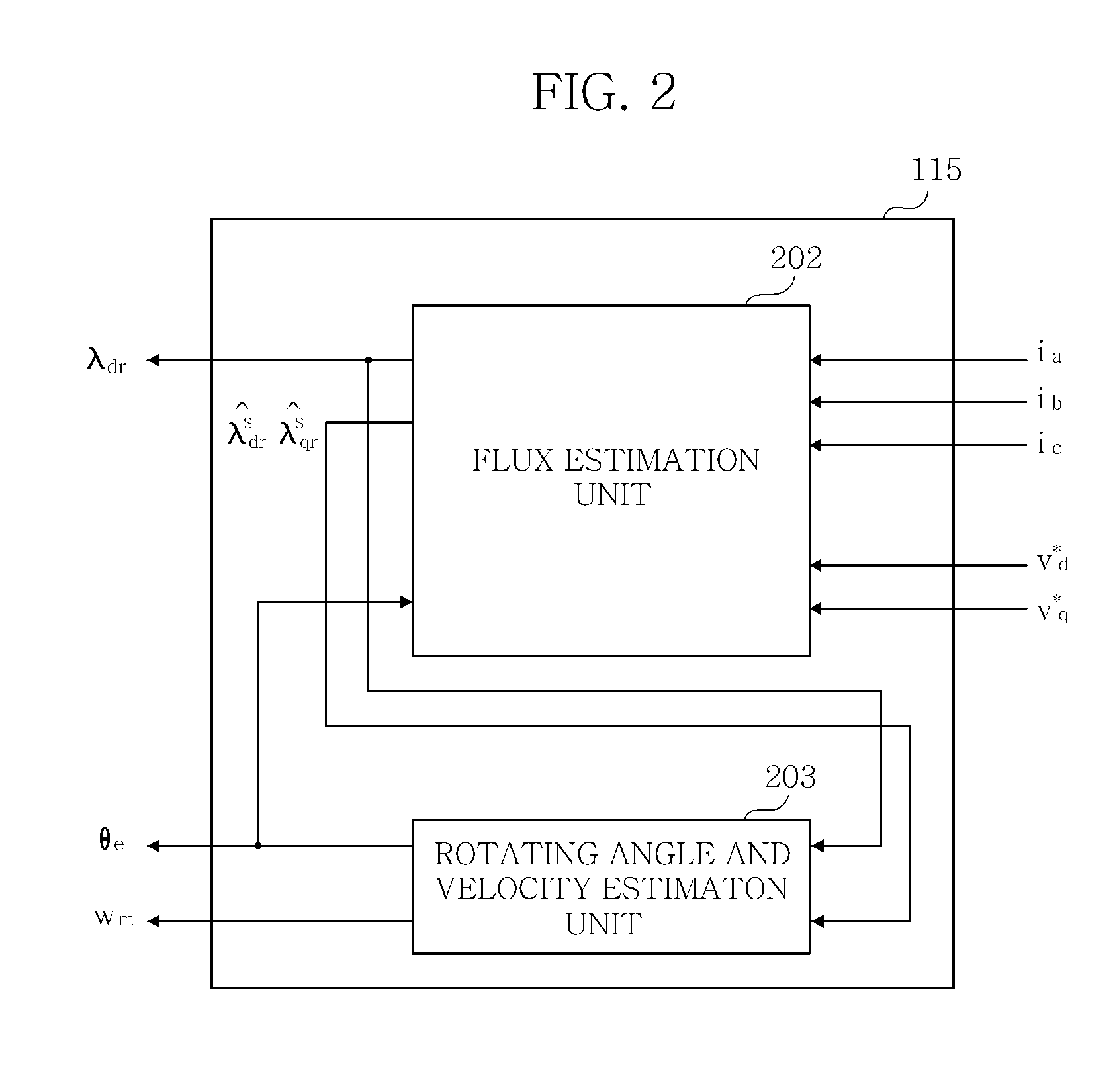
[0043]In order to accomplish the object, there is provided a flux controller for an induction motor using a sensorless vector control method, the controller comprising a velocity controller for receiving a difference in velocity between a velocity command and an estimated velocity to output a torque current command, a torque current controller for receiving the torque current command to output a torque voltage command, a flux controller for receiving a difference in flux between a flux command and an estimated flux value to output a flux current command, a flux current controller for receiving the flux current command to output a flux voltage command, a three-phase converter for converting the torque voltage command and the flux voltage command into a three-phase voltage command applied to the induction motor to output the three-phase voltage command, a flux estimator for receiving a three-phase current of the induction motor, the torque voltage command and the flux voltage command to output a rotating angle of a rotor of the induction motor, an estimated flux value of the rotor and an estimated velocity of the rotor, and a flux regulator for receiving the torque voltage command and the estimated velocity to output a gain value that regulates a magnitude of the flux command, wherein the flux regulator increases the magnitude of the flux command when a rotating velocity of the rotor is low. Therefore, the flux controller is advantageous in that a magnitude of torque command voltage is not reduced below a predetermined value, so that flux estimation performance can maintain reliability even at low velocity.

Problems solved by technology

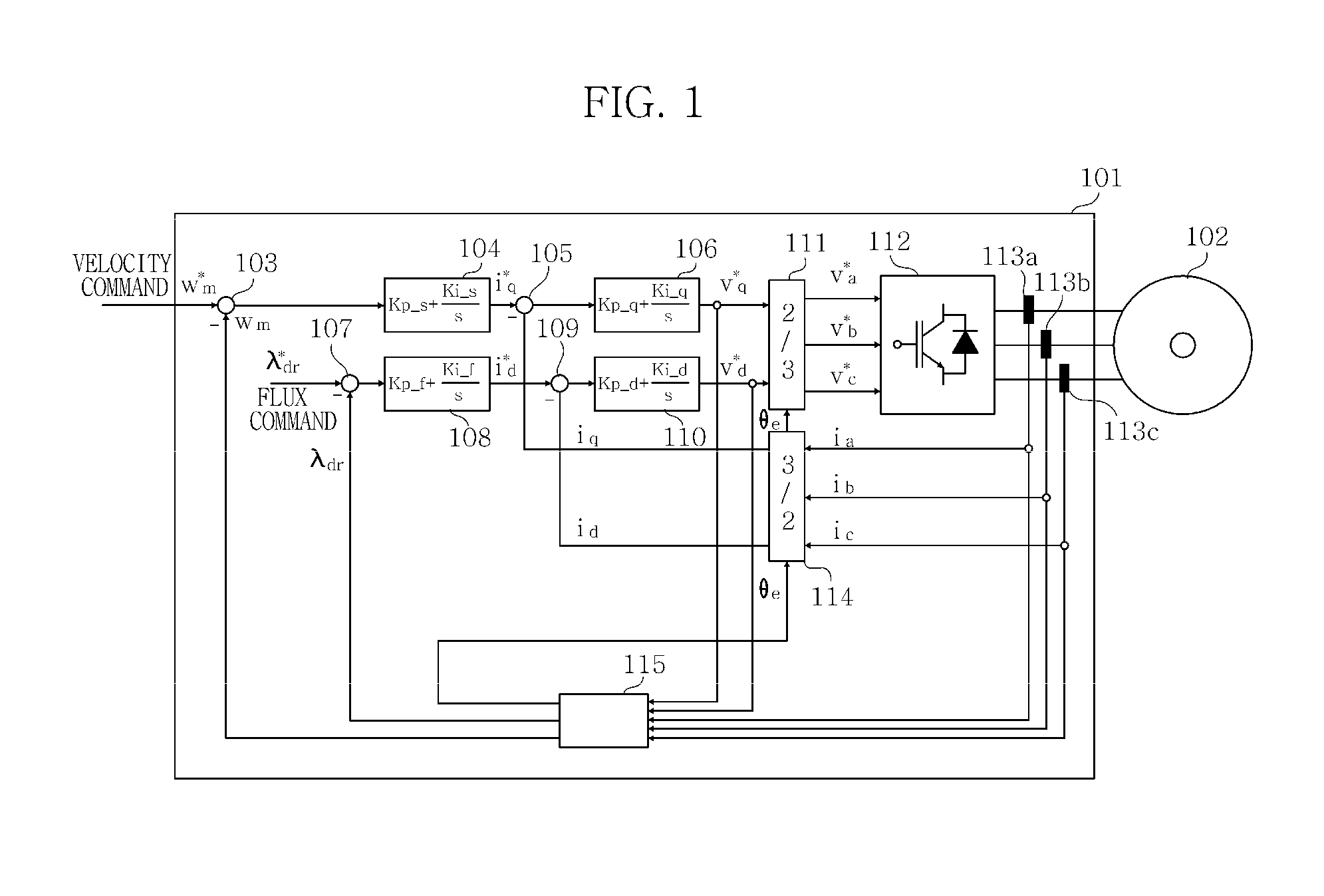
However, the sensorless vector control method is problematic in that voltage required to drive a motor in the low velocity region is reduced, so that voltage (inverter output voltage) inputted into the motor may be erroneously estimated due to offset or dead time, whereby flux estimation performance is deteriorated.
Consequently, the sensorless vector control method fails to exhibit sufficient performance in the low velocity region in comparison with a high velocity region.
However, if the voltage and current values used in the equations (8) and (9) include offset, an integrator leads to a divergence, thus making it difficult to use in practical.
However, in a low velocity region where a back electromotive force is small, so that the magnitude of the inverter output voltage is not sufficiently greater than that of the offset voltage, the operation of the equations (8) and (9) is affected by the offset, thus resulting in the divergence.
However, such a method is problematic in that the time constant of the filter must be reduced in a region having a very low frequency, so that it is difficult to expect good flux estimation performance because of the characteristics of the high pass filter such as a phase delay resulting from the reduced time constant.
In the low velocity region where the magnitude of voltage is reduced, an error in voltage caused by dead time affects the estimation of the flux, so that there occurs a difference between command voltage used in the calculation of flux and voltage inputted actually into the motor.
The difference leads to an error in the flux estimation.

Method used


Image

  • Flux controller for induction motor
  • Flux controller for induction motor
  • Flux controller for induction motor

Examples


Embodiment Construction

[0056]Hereinafter, a flux controller according to the present invention will be described in detail with reference to the accompanying drawings.

[0057]FIG. 4 is a block diagram illustrating a configuration of an induction motor system that is equipped with a flux controller according to the present invention and is driven at variable velocity by a sensorless vector control method without a velocity and position sensor.

[0058]According to a concept of the present invention, a flux regulator 416 is disposed in an inverter 401 to maintain flux estimation performance in a low velocity region. The flux regulator 416 receives a present motor velocity Wm from a sensorless flux estimator 415, and receives a torque voltage command V*q from a flux current controller 406. Further, the flux regulator 416 outputs a gain to a multiplier 417. Here, the gain regulates a magnitude of a flux command inputted into a subtractor 407 for calculating a flux error.

[0059]The multiplier 417 multiplies the gain...


PUM


Abstract

Disclosed is a flux controller for maintaining reliable flux estimation performance in a low velocity region, the controller including a velocity controller, a torque current controller for outputting a torque voltage command, a flux controller for outputting a flux current command, a flux current controller for receiving the flux current command to output a flux voltage command, a three-phase converter for converting the torque voltage command and the flux voltage command into a three-phase voltage command applied to the induction motor to output the three-phase voltage command, a flux estimator for outputting a rotating angle of a rotor of the induction motor, an estimated flux value of the rotor and an estimated velocity of the rotor, and a flux regulator for receiving the torque voltage command and the estimated velocity to output a gain value that regulates a magnitude of the flux command.

Description

CROSS-REFERENCE TO RELATED APPLICATION[0001]This application claims the benefit of Korean Patent Application No. 10-2010-0120433, filed Nov. 30, 2010, the disclosure of which is hereby incorporated herein by reference in its entirety.BACKGROUND OF THE INVENTION[0002]1. Field of the Invention[0003]The present invention relates generally to a flux controller for an induction motor and, more particularly, to a flux control apparatus capable of minimizing a decline in flux estimation performance in a low velocity region in a drive inverter system of an induction motor using a sensorless vector control method.[0004]2. Description of the Related Art[0005]Generally, methods for driving an induction motor at variable velocity without using a velocity sensor or a position sensor includes a constant voltage / frequency (VF) control method that is an open loop control method, and a sensorless vector control method that estimates a flux position of a motor rotor from measurements of a voltage, a ...

Claims


Application Information

Patent Timeline
IPC IPC(8): H02P21/08
CPCH02P21/146H02P21/141H02P21/18
Inventor HONG, CHAN OOK
Owner LSIS CO LTD
Learn More