
Scheme for transmitting reference signal in wireless communication system

a wireless communication system and reference signal technology, applied in the field of wireless communication system reference signal scheme, can solve the problems of reducing the performance of the ue, non-uniform cell distribution, and limited estimation, so as to maximize the estimation performance of the transmission scheme information, improve system capacity, and improve the estimation capability of the transmission scheme

Active Publication Date: 2018-08-21
SAMSUNG ELECTRONICS CO LTD
View PDF11 Cites 0 Cited by
  • Summary
  • Abstract
  • Description
  • Claims
  • Application Information

AI Technical Summary

Benefits of technology

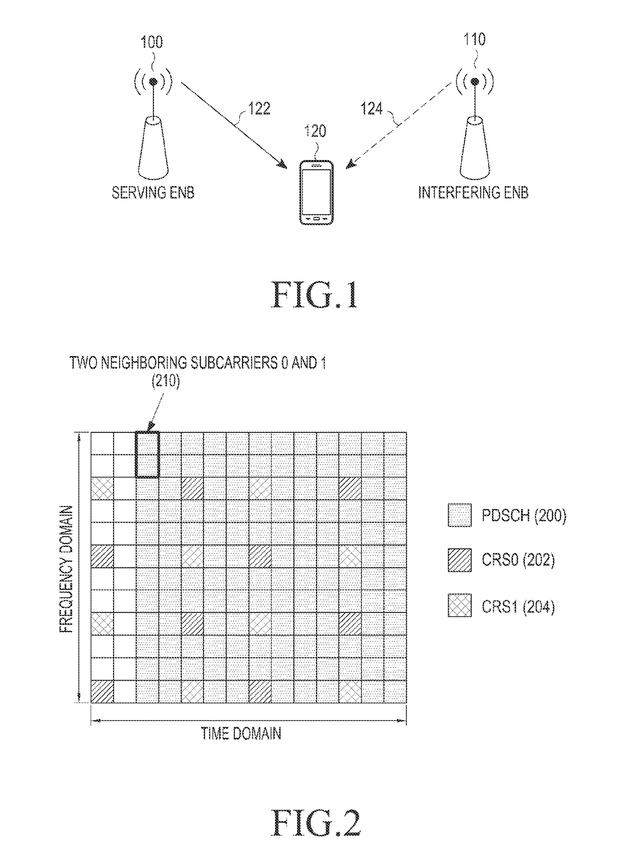
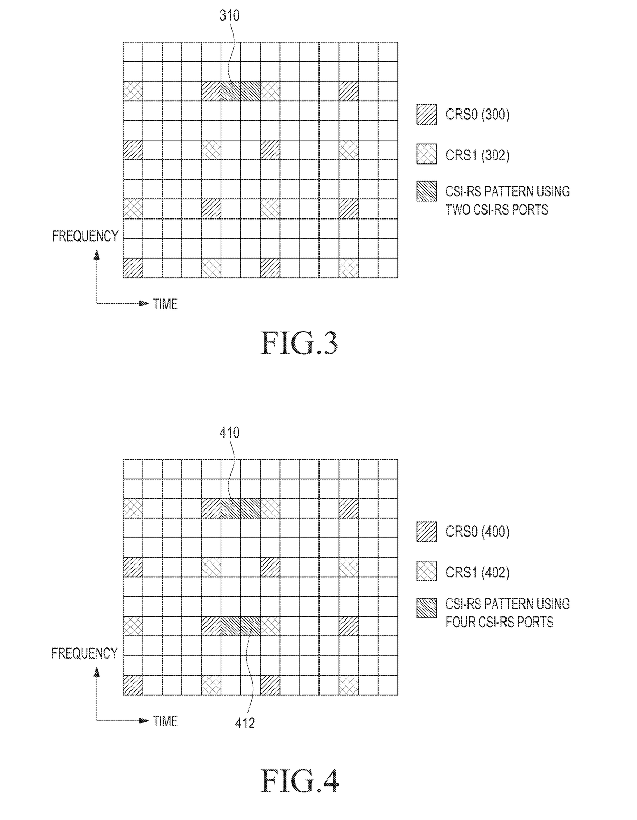
The present disclosure provides a new method for estimating the information of interference signals in a wireless communication system. This method takes into account the transmission scheme used and maximizes the performance of estimating the interference signal information. The disclosure also provides a new reference signal for estimating the transmission scheme information of interference signals, which can be used by the next generation UE to remove interference. The method improves system capacity and enhances the estimation capability of transmission schemes, such as SFBC, SFBC-FSTD, and CDD-SM. It also minimizes errors caused by interference signals and improves interference removal.

Problems solved by technology

When various types of cells, such as conventional cells and femtocells operate in the same environment, non-uniform cell distribution occurs.
In such an environment, inter-cell interference is the largest factor increasing packet error, thus reducing performance in the UE.
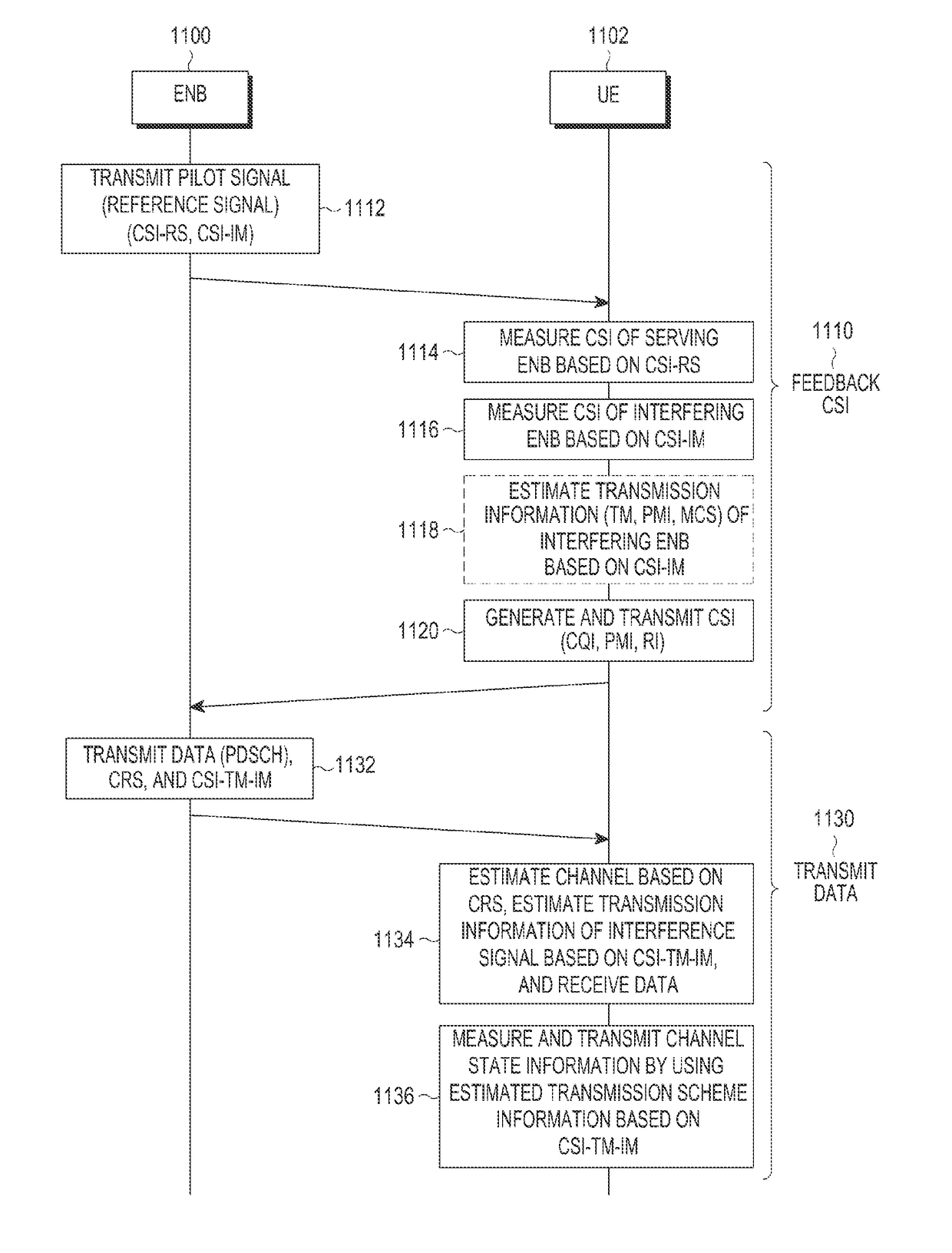
While transmission scheme information of the interference signal may be estimated using the CSI-IM-, such estimation is limited because the CSI-IM reuses the CSI-RS resource pattern which is not suitable to estimate transmission schemes.

Method used


Image

  • Scheme for transmitting reference signal in wireless communication system
  • Scheme for transmitting reference signal in wireless communication system
  • Scheme for transmitting reference signal in wireless communication system

Examples


Embodiment Construction

[0029]Hereinafter, embodiments of the present disclosure will be described in detail with reference to the accompanying drawings. In the following description of the present disclosure, detailed descriptions of known configurations or functions incorporated herein will be omitted when not necessary for one of ordinary skill in the art and / or where such a detailed description may make the subject matter of the present disclosure unclear. Terms described herein are used and / or defined in consideration of the functions of the present disclosure, but the terminology, as well as the specific implementations thereof, may vary according to the intention or convention of a user or operator. Therefore, the definitions of the terms should be determined based on the contents throughout the specification and the knowledge of one of ordinary skill in the art, and not be interpreted so as to limit the overall disclosure or the scope of the claims appended hereto in any way.

[0030]In the detailed d...


PUM


Abstract

Methods, systems, apparatuses, evolved NodeB (EnBs), User Equipment (UE), and chip sets for all of the same, in cellular communication systems are described. One method for a UE includes receiving a Channel State Information Reference Signal (CSI-RS) transmitted by an eNB according to a pattern in a time-frequency resource grid determined based on the transmission scheme of the eNB, measuring the state of the transmission channel using the CSI-RS, generating channel state information based on the measuring, and transmitting the channel state information as feedback. The UE receives a downlink signal including data and a Cell-specific Reference Signal (CRS) from the eNB and estimates the transmission channel using the CRS and then acquires the data using the estimated channel.

Description

PRIORITY[0001]This application claims priority under 35 U.S.C. § 119(e) to U.S. Provisional Patent Application Ser. No. 62 / 002,452, filed on May 23, 2014, and under 35 U.S.C. § 119(a) to Korean Patent Application Nos. 10-2015-0021130 and 10-2015-0034799, filed on Feb. 11, 2015 and Mar. 13, 2015, respectively, all of which are incorporated herein by reference for all purposes as if fully set forth herein.BACKGROUND OF THE DISCLOSURE[0002]1. Field of the Disclosure[0003]The present disclosure relates to a scheme for transmitting a reference signal in a wireless communication system, and more particularly to a method and an apparatus for transmitting a reference signal in the light of an interference signal in a cellular communication system.[0004]2. Description of the Related Art[0005]In next generation wireless communication systems (for example, the Long Term Evolution-Advanced (LTE-A) system), cell coverage is relatively small when compared to conventional cellular environments. Wh...

Claims


Application Information

Patent Timeline
Patent Type & Authority Patents(United States)
IPC IPC(8): H04L1/00H04W72/04H04L5/00H04B7/06H04L1/06H04W24/08H04W72/08H04L25/02H04W72/54
CPCH04W72/082H04B7/0619H04B7/0623H04B7/0626H04B7/0632H04B7/0639H04B7/0667H04B7/0669H04B7/0671H04B7/0684H04B7/0689H04L1/06H04L5/0048H04L25/02H04W24/08H04W72/042H04B7/068H04L1/0026H04L23/00H04W72/541H04W72/23
Inventor LEE, HEUN-CHULKIM, DONG-SIKLEE, HYO-JINLIM, JONG-HAN
Owner SAMSUNG ELECTRONICS CO LTD
Learn More