
Wireless communication apparatus and frequency hopping method

Active Publication Date: 2012-03-08
SUN PATENT TRUST
View PDF9 Cites 61 Cited by
  • Summary
  • Abstract
  • Description
  • Claims
  • Application Information

AI Technical Summary

Benefits of technology

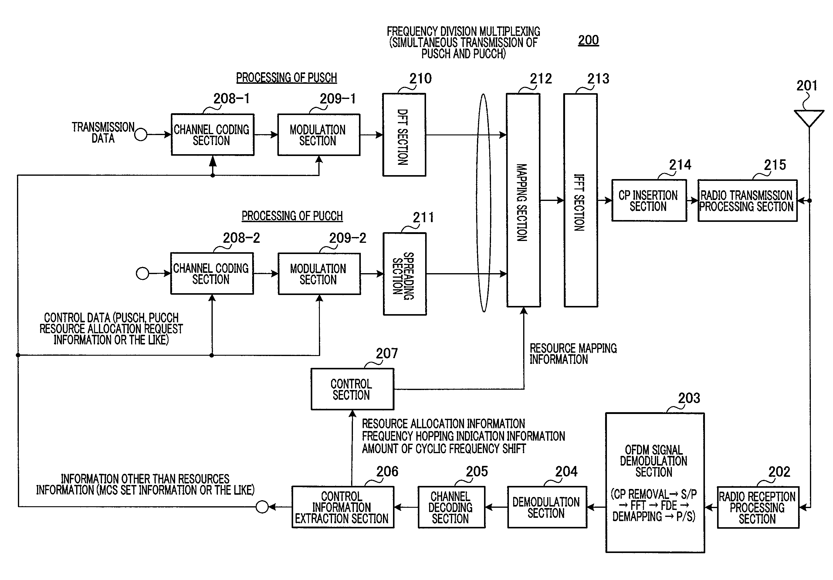
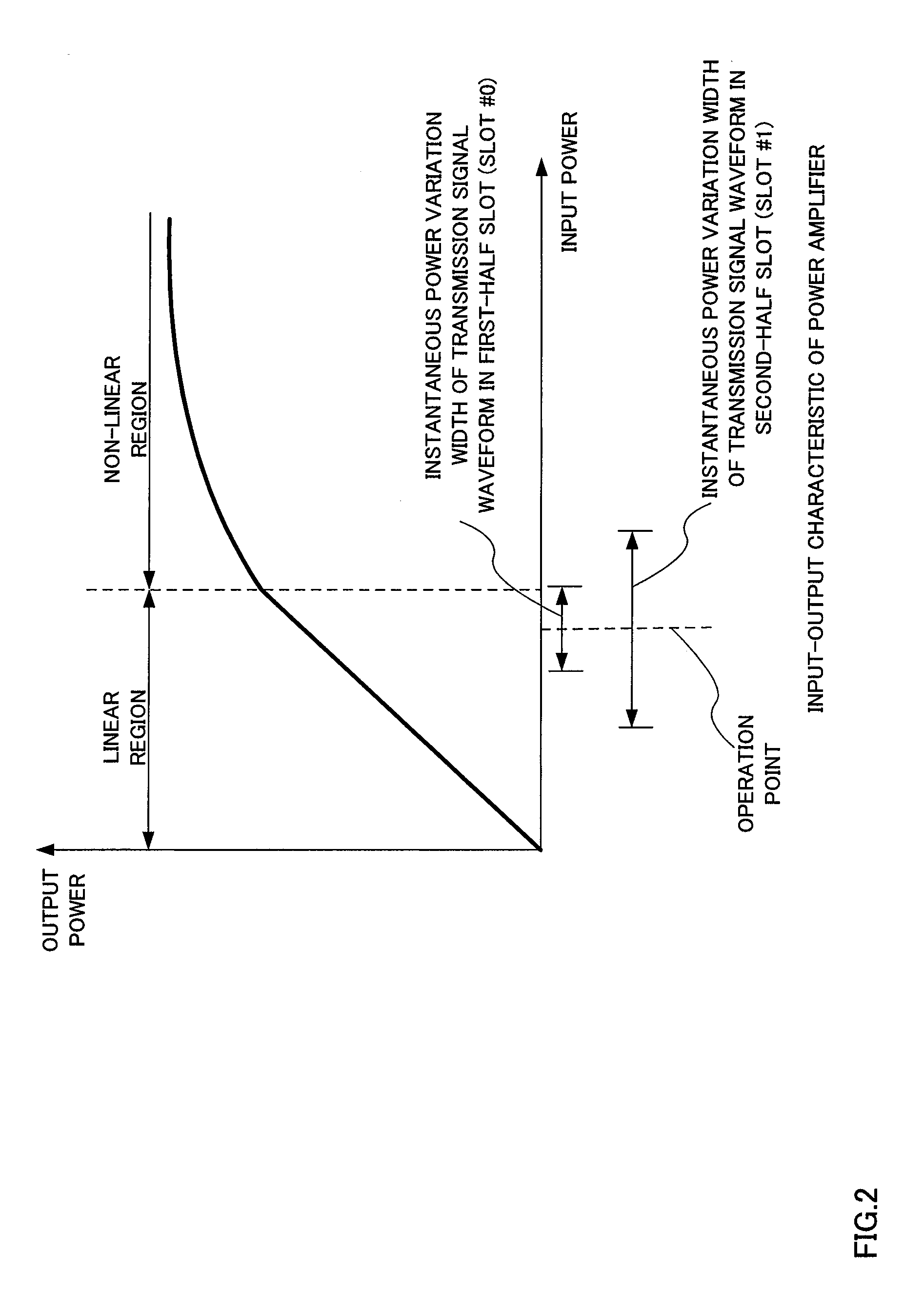
[0031]The present invention frequency division multiplexes and transmits a plurality of channels, and can thereby suppress changes in an instantaneous power distribution characteristic of a time waveform of a transmission signal in a predetermined time segment in which the signal is transmitted in a predetermined transmission format (MCS set or transmission power control value) while suppressing the deterioration of the frequency utilization efficiency and throughput.

Problems solved by technology

However, due to the influence of limitations to the above-described PUSCH and PUCCH frequency resource allocation and mapping method, there is a problem that flexibility of UL frequency resource allocation is low, and therefore the following method is under study about LTE-advanced UL SC-FDMA transmission (see Non-Patent Literature 1 and Non-Patent Literature 2).

Method used


Image

  • Wireless communication apparatus and frequency hopping method
  • Wireless communication apparatus and frequency hopping method
  • Wireless communication apparatus and frequency hopping method

Examples


embodiment 1

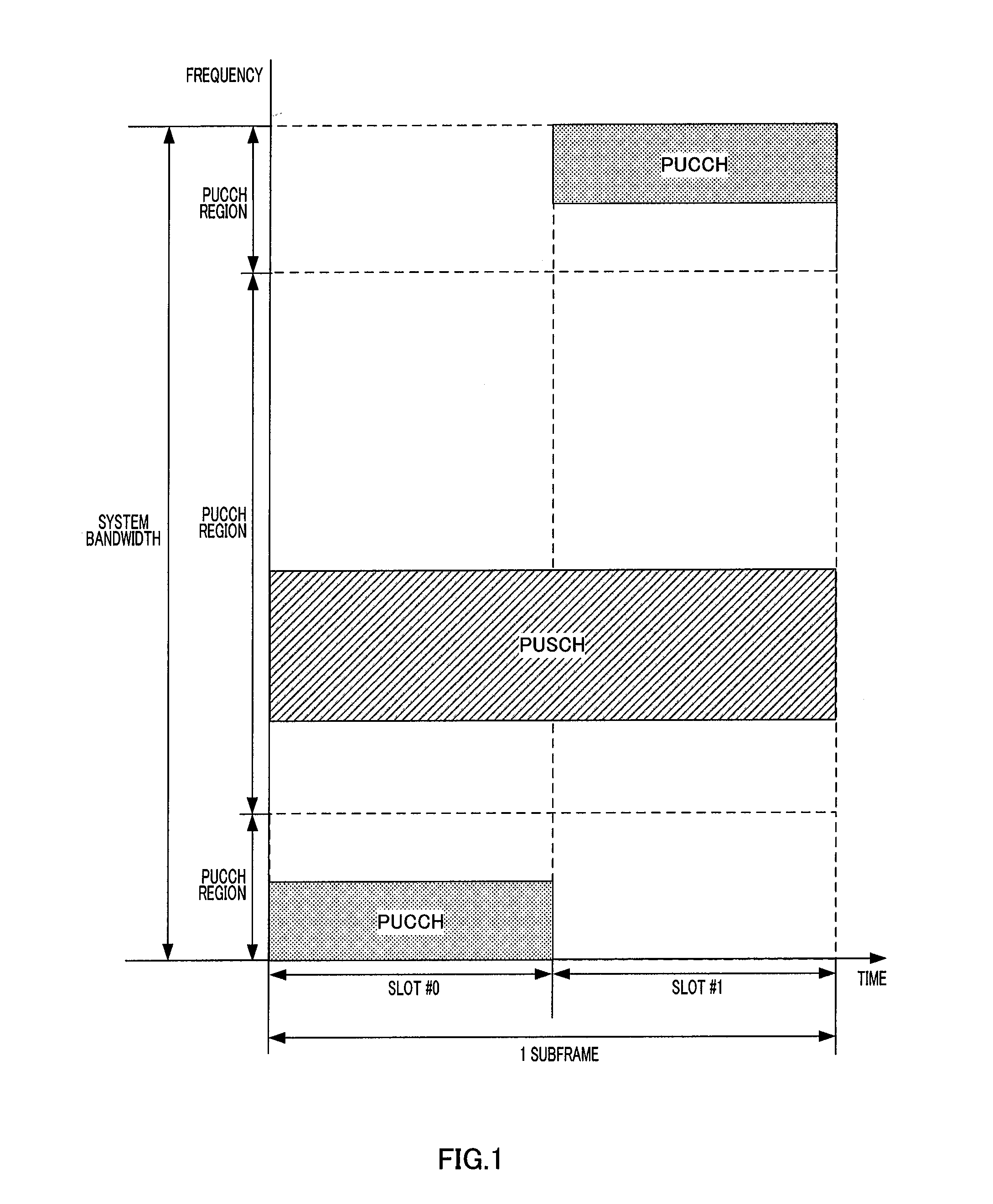
[0079]When the frequency interval between a first channel and a second channel allocated to the first slot in an IDFT (Inverse Discrete Fourier Transform) or IFFT (Inverse Fast Fourier Transform) band is B, the present embodiment cyclically allocates the second channel to a frequency resource in the second slot located B apart from the first channel within the IDFT or IFFT bandwidth.

[0080]Here, the IDFT or IFFT band may be called “system (component band) band.” In an LTE-A system, to simultaneously realize communication at an ultra-high speed several times the transmission rate in the LTE system and backward compatibility for the LTE system, the band for the LTE-A system is divided into “component bands” of 20 MHz or below, which is a bandwidth support by the LTE system. That is, the “component band” is a band having, for example, a width of maximum 20 MHz and defined as a base unit of a communication band. Furthermore, the “component band” may also be expressed as “component carrie...

embodiment 2

[0252]A case has been described in Embodiment 1 where when the frequency interval between the first channel and second channel allocated to the first slot is B within the IDFT or IFFT band, frequency division multiplexing transmission is performed based on the resource allocation rule whereby the second channel is cyclically allocated to a frequency resource located B apart from the first channel in the second slot within the IDFT or IFFT band (system band) width. The present embodiment will describe a method of setting frequency interval (frequency difference) B between a plurality of channels subjected to frequency division multiplexing transmission according to the resource allocation rule. For frequency interval B in the second slot, the same value as frequency interval B in the first slot is maintained as described in Embodiment 1.

[0253][Frequency Interval Setting Method #1-0]

[0254]Of the first channel or second channel frequency-division-multiplexed and transmitted in the firs...

embodiment 3

[0282]The present embodiment reuses the method in LTE Re1.8 that applies frequency hopping to PUCCH and PUSCH independently of each other according to the resource allocation rule for frequency division multiplexing and transmitting PUSCH and PUCCH. Furthermore, the present embodiment generates a coordinated frequency hopping pair of PUSCH and PUCCH according to the number of subbands included in the system band and resource numbers of frequency resources on which PUCCH is arranged in the first slot.

[0283]The number of subbands is set by the base station. The base station sets the number of subbands so that the bandwidth of subbands obtained by dividing the band of the system band to which frequency hopping is applied is, for example, a natural number multiple of an RBG (Resource Block Group) size. Information of the number of subbands set by the base station is included, for example, in frequency hopping indication information (or signaling information of a higher layer (RRC (Radio...


PUM


Abstract

Disclosed are a wireless communication apparatus and frequency hopping method which minimize the change in the instantaneous power distribution characteristics of the time waveform of transmission signals when a plurality of channels are multiplexed by frequency division. At a terminal (200), a mapping unit (212) maps the PUCCH to frequency resources of a first slot, maps the PUSCH to frequency resources, among the frequency resources of the first slot, separated exactly by predetermined frequency spacing (B) from the frequency resources to which the PUCCH is mapped, and cyclically shifts the frequencies so as to map the PUCCH and PUSCH to frequency resources, within an IDFT or IFFT bandwidth, of a second slot while maintaining the predetermined frequency spacing (B), thereby allowing frequency hopping of the PUCCH and PUSCH between the first slot and the second slot.

Description

TECHNICAL FIELD [0001]The present invention relates to a radio communication apparatus and a frequency hopping method for frequency division multiplexing and transmitting a plurality of channels.BACKGROUND ART [0002]3GPP (Generation Partnership Project) is studying standardization of LTE-advanced as a mobile communication system which becomes a successor of LTE (Long Term Evolution). LTE-advanced has decided to adopt DFT-spread OFDM (DFT-S-OFDM) using DFT (Discrete Fourier Transform) precoding which is also adopted in LTE as an uplink (UL) radio access scheme or SC-FDMA (Single-Carrier Frequency Division Multiple Access).[0003]In LTE UL transmission using SC-FDMA, the following method is adopted as a frequency resource allocation and mapping method of UL physical channel (physical uplink shared channel (PUSCH), physical uplink control channel (PUCCH)) that transmits a data signal and control signal to improve transmission quality while maintaining low PAPR (Peak-to-Average Power Rat...

Claims


Application Information

Patent Timeline
IPC IPC(8): H04B1/713H04W72/04H04J11/00
CPCH04B1/713H04L5/0012H04L5/0005H04W72/042H04J1/02H04L27/2605H04J13/0059H04W72/23
Inventor TAKAOKA, SHINSUKEIMAMURA, DAICHINAKAO, SEIGO
Owner SUN PATENT TRUST
Learn More