
Laser diode based multiple-beam laser spot imaging system for characterization of vehicle dynamics

a laser spot imaging and laser diode technology, applied in the direction of speed/acceleration/shock measurement, speed/acceleration/shock measurement, speed/acceleration/shock measurement, etc., can solve the problems of laser failure and severe contamination, and achieve the effect of sufficient contrast, enhanced system accuracy, and particularly sensitive measurement of laser device distance to the reference surfa

Active Publication Date: 2012-02-23
TRUMPF PHOTONIC COMPONENTS GMBH
View PDF29 Cites 24 Cited by
  • Summary
  • Abstract
  • Description
  • Claims
  • Application Information

AI Technical Summary

Benefits of technology

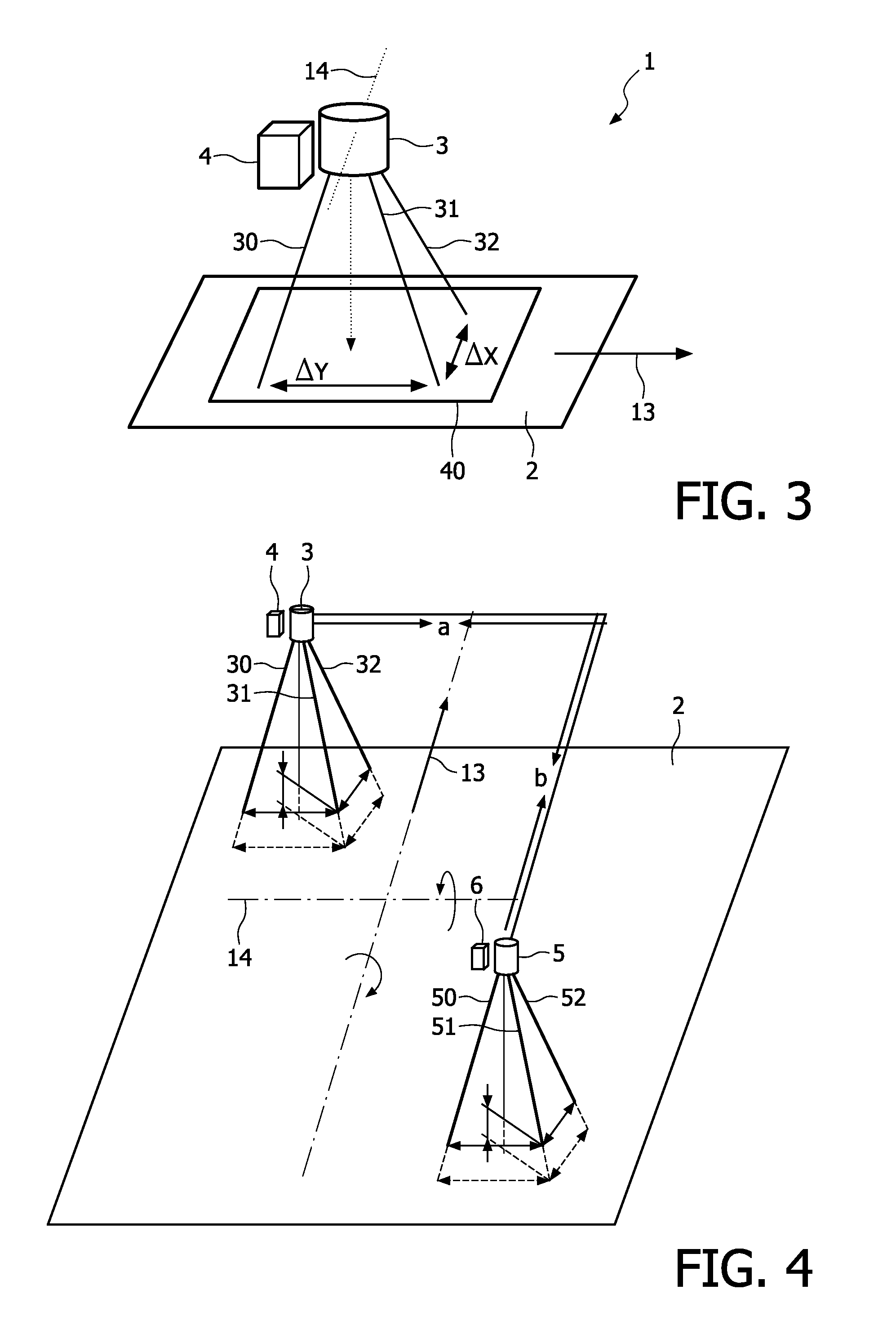
[0005]In combination with a laser self-mixing ground speed sensor, the multiple-beam laser spot imaging system according to the invention can significantly improve the absolute accuracy of vehicles' ground speed measurement. Pitch and roll angles derived from the laser imaging system can be implemented in a rotation matrix to correct the systematic error of the ground speed measurement.
[0034]According to a further alternative or additional embodiment, the laser diode is operated in a pulsed mode (e.g. square wave), temporally synchronized imaging further improves the contrast ratio of the laser spots. In particular, a pulsed power supply for the laser device is provided for pulsing the laser beams. The imaging device is synchronized with the pulsed power supply so that images are acquired during a pulse and between two pulses. To suppress the background signal, the data processing unit can simply subtract the images.

Problems solved by technology

Abnormal changes indicate laser failure, out-of-focus sensing beam, severe contaminations to sensor exit or entrance window or presence of extremely low reflectance roads.

Method used


Image

  • Laser diode based multiple-beam laser spot imaging system for characterization of vehicle dynamics
  • Laser diode based multiple-beam laser spot imaging system for characterization of vehicle dynamics
  • Laser diode based multiple-beam laser spot imaging system for characterization of vehicle dynamics

Examples


Embodiment Construction

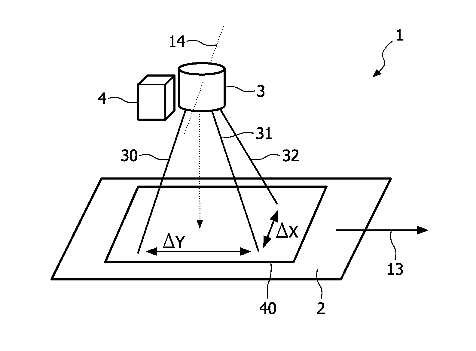
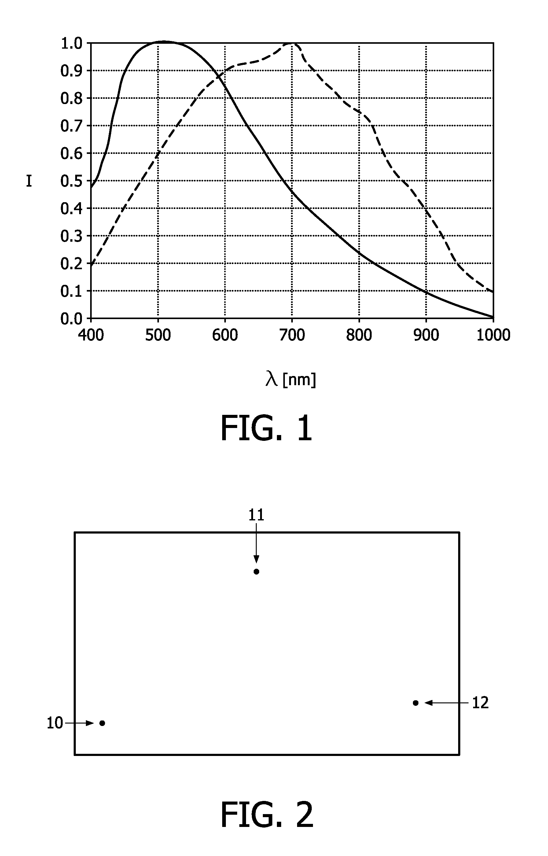
[0041]The optical vehicle laser sensor system for detection of vehicle dynamics parameters according to the invention is based on a laser device which generates three spatially separated laser beams directed onto the road surface, so that three laterally separated laser spots on the road surface are produced. An imaging device with a matrix sensor images the laser spots. The speed of the vehicle is determined from Doppler-induced self-mixing laser intensity oscillations. The laser sensor system further comprises a data processing device for calculating lateral distances between the imaged laser spots, and determining the orientation of the optical vehicle laser sensor system with respect to the road surface, or the vehicle's orientation with respect to the road, respectively.

[0042]A VCSEL emitting in the infrared spectral region between 800 and 1000 nanometers wavelength is particularly preferred as laser diode. Although VCSEL beams of self-mixing ground speed sensors are in this ca...


PUM


Abstract

The invention is related to a laser diode based multiple beam laser spot imaging system for characterization of vehicle dynamics. A laser diode based, preferably VCSEL based laser imaging system is utilized to characterize the vehicle dynamics. One or more laser beams are directed to the road surface. A compact imaging system including an imaging matrix sensor such as a CCD or CMOS camera measures locations or separations of individual laser spots. Loading status of vehicles and vehicles' pitch and roll angle can be characterized by analyzing the change of laser spot locations or separations.

Description

FIELD OF THE INVENTION[0001]The invention generally concerns measurements of vehicle dynamics such as speed and roll angle. More specifically, the invention relates to optical measurements of vehicle dynamics.BACKGROUND OF THE INVENTION[0002]It is known that laser self-mixing interference (SMI) can be used for speed and distance measurements, see G. Giuliani, M. Norgia, S. Donati, T. Bosch “Laser Diode Self-mixing Technique for Sensing Applications” in Journal of Pure and Applied Optics, 6 (2002), page 283-294. It is also known that vertical cavity surface emitting laser (VCSEL) with integrated photodiode is particularly suitable for SMI sensing applications. However, a general problem with speed measurements using self-mixing sensors is that the orientation of the sensor with respect to the road directly influences the measurement. As the vehicle frequently changes its orientation with respect to the road, e.g., due to a declination of the vehicle body induced by centrifugal forces...

Claims


Application Information

Patent Timeline
Patent Type & Authority Applications(United States)
IPC IPC(8): G01P3/36B60W40/11B60W40/112B60W40/114
CPCB60T8/172B60T2250/04B60W40/11B60W40/112G01S17/58G01P3/366G01P21/02G01S7/48G01S17/06B60W40/114
Inventor HAN, MENG
Owner TRUMPF PHOTONIC COMPONENTS GMBH
Learn More