
Inertial measurement system and method with bias cancellation

a technology of inertial measurement and bias cancellation, applied in the field ofinertial measurement, can solve the problems of inability to accurately detect the accuracy of the inertial measurement, the use of more expensive sensors with very low residual offset errors, and the inability to reduce the sensitivity of alignment errors, so as to improve the signal-to-noise ratio, enhance the accuracy of such a system, and reduce the sensitivity effect of alignment errors

Active Publication Date: 2009-01-27
EMCORE INC
View PDF13 Cites 16 Cited by
  • Summary
  • Abstract
  • Description
  • Claims
  • Application Information

AI Technical Summary

Benefits of technology

"The invention provides a new and improved system and method for inertial measurement that cancels out bias offset. The system uses one or more inertial sensors that have their input axes modulated in orientation about a perpendicular axis, and in some cases, the accuracy of the system is enhanced to improve signal-to-noise ratio and reduce sensitivity to errors in alignment."

Problems solved by technology

This non-zero output is called bias, and it can cause significant errors in inertial measurements.
In applications with stringent limits on offset errors, more expensive sensors with very low residual offset errors must generally be used, and those sensors are often relatively large and heavy.
Heretofore, there have been some attempts to eliminate offset errors by rotating a gyro about the input axis of the sensor, which is bad because it produces a rotation rate signal that must be dealt with.
However, it is not always feasible or even desirable to apply a constant rotation to such instruments.
However, as noted above, rotating a sensor about its input axis is undesirable because it provides an angular rate input other than the one to be detected.

Method used


Image

  • Inertial measurement system and method with bias cancellation
  • Inertial measurement system and method with bias cancellation
  • Inertial measurement system and method with bias cancellation

Examples


Embodiment Construction

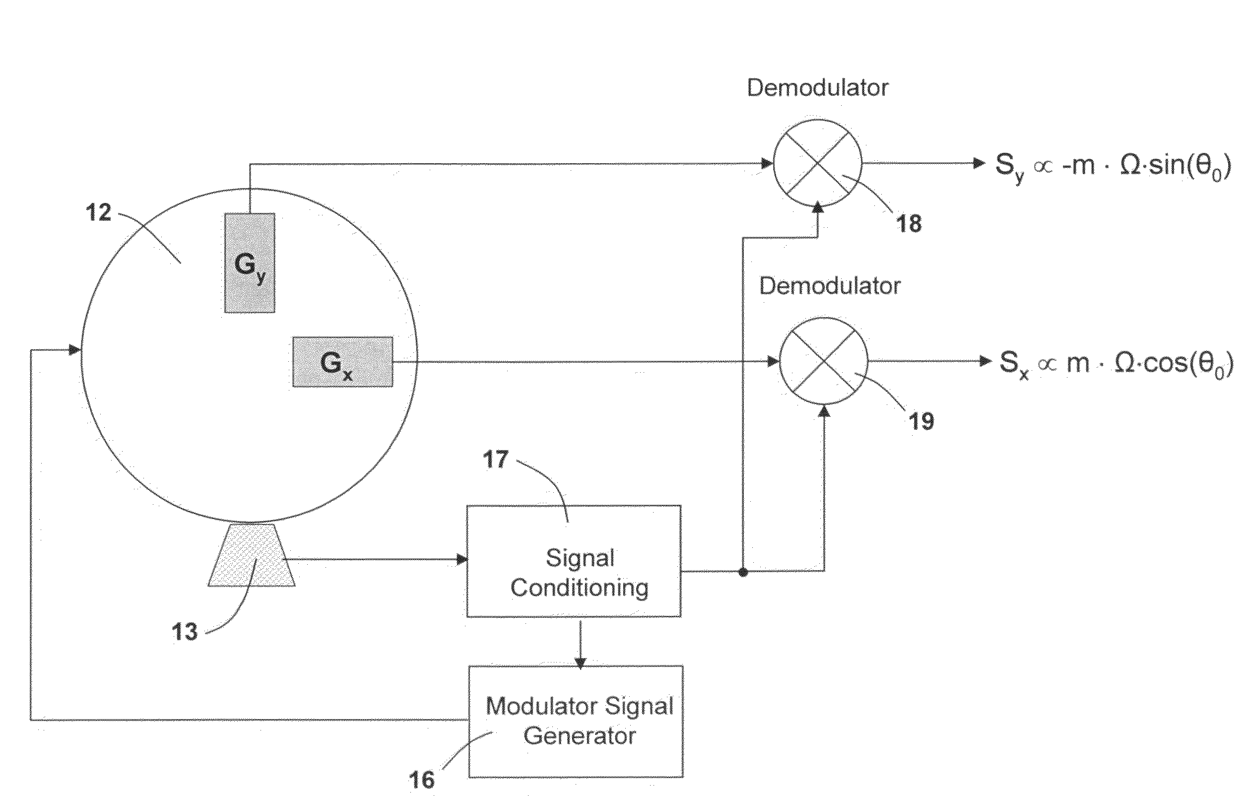
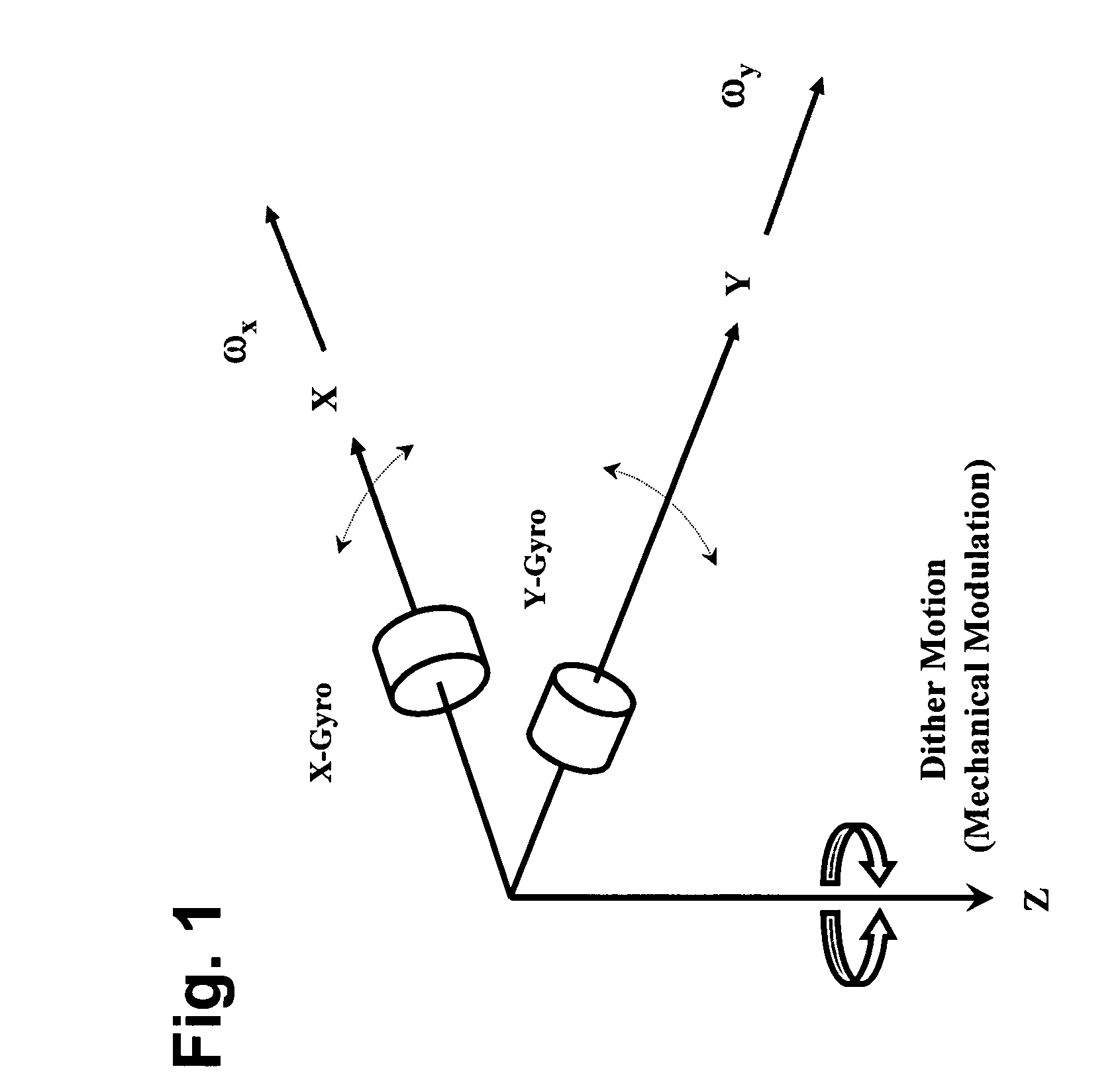
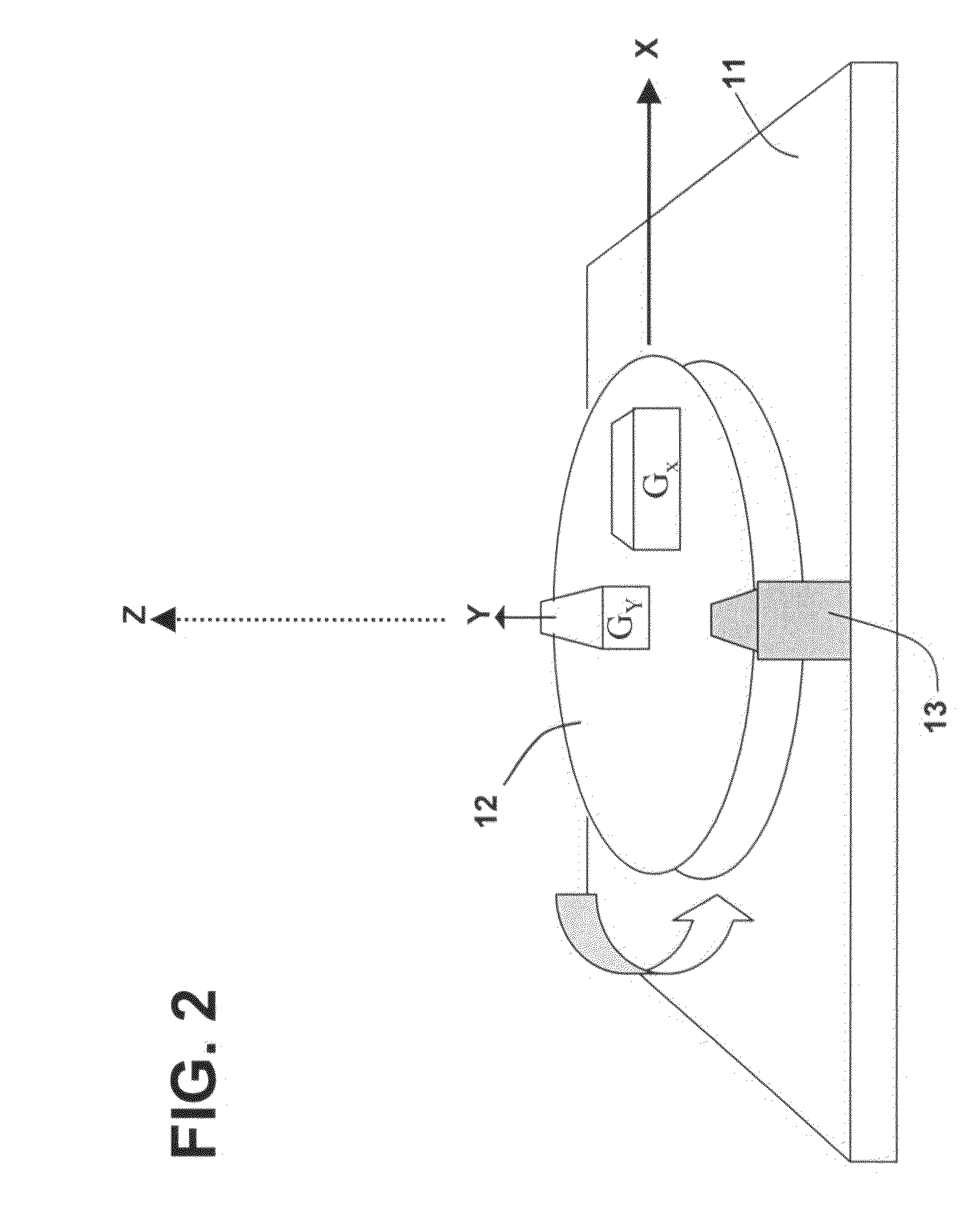
[0023]As illustrated in FIG. 1, two angular rate sensors or gyroscopes X-Gyro and Y-Gyro have their input axes aligned with the x- and y-axes, respectively. Input axis modulation or dither introduces an oscillatory rotation about the z-axis which is perpendicular to the input axes. The dither oscillation can range in frequency from a few milliHertz to 100 Hertz, or more, depending upon the type of dithering motion employed, with lower frequencies being used for square wave modulation or two-point indexing dither and higher frequencies being used with sinusoidal and other periodic waveforms. The magnitude of the dither is typically on the order of a few milliradians to 20 degrees, but it can potentially be as high as ±90 degrees if input axis reversal is desired.

[0024]The dithering motion causes the input axes of the two rate sensors or gyros to rotate with respect to fixed inertial reference axes, with the change in angular alignment of the sensor axes being equal to the instantaneo...


PUM


Abstract

System having one or more inertial sensors in which one or more of the sensor input axes are modulated in orientation about an axis substantially perpendicular to the input, or sensitive, axis of the sensor and, in some embodiments, by also enhancing the accuracy of such a system to provide improved signal to noise ratio and reduced sensitivity to errors in alignment of the sensor axes to the dither axes.

Description

CROSS-REFERENCE TO RELATED APPLICATIONS [0001]Continuation-in-Part of Ser. No. 11 / 072,064, now U.S. Pat. No. 7,191,636. Also based on Provisional Application No. 60 / 785,911, filed Mar. 24, 2006, the priority of which is also claimed.BACKGROUND OF THE INVENTION [0002]1. Field of Invention[0003]This invention pertains generally to inertial measurement, and, more particularly, to an inertial measurement system and method in which the fixed bias offset of rate sensors or gyroscopes is cancelled.[0004]2. Related Art[0005]Angular rate sensors or gyroscopes (gyros) exhibit a non-zero output in the absence of rotation about the input axis. This non-zero output is called bias, and it can cause significant errors in inertial measurements. The magnitude of the error depends upon the type of sensor or gyroscope used. In applications with stringent limits on offset errors, more expensive sensors with very low residual offset errors must generally be used, and those sensors are often relatively l...

Claims


Application Information

Patent Timeline
Patent Type & Authority Patents(United States)
IPC IPC(8): G01C19/00G01C25/00G01C19/02
CPCG01C21/16G01C25/005G01C21/183
Inventor MOORE, ROBERT H.SHIRASAKA, ICHIROJAFFE, RANDALL
Owner EMCORE INC
Learn More