
Solar battery and production method thereof

a solar battery and production method technology, applied in the direction of semiconductor devices, non-conductive materials with dispersed conductive materials, pv power plants, etc., can solve the problems of reducing yield, complex process for producing solar battery modules, and increasing the cost of solar energy storage, so as to achieve easy and efficient production of solar energy, reduce environmental load, and high conversion efficiency and reliability

Inactive Publication Date: 2012-02-09
FUJIFILM CORP
View PDF0 Cites 14 Cited by
  • Summary
  • Abstract
  • Description
  • Claims
  • Application Information

AI Technical Summary

Benefits of technology

[0010]The present invention solves the conventional problems and achieves the following object. That is, the present invention provides a solar battery having high conversion efficiency and reliability, and a method for producing a solar battery, which does not require soldering, causes less load on environment, and can inhibit cracks and warpage of the solar battery element, and separation of an interconnector, thereby producing the solar battery with ease and efficiency.
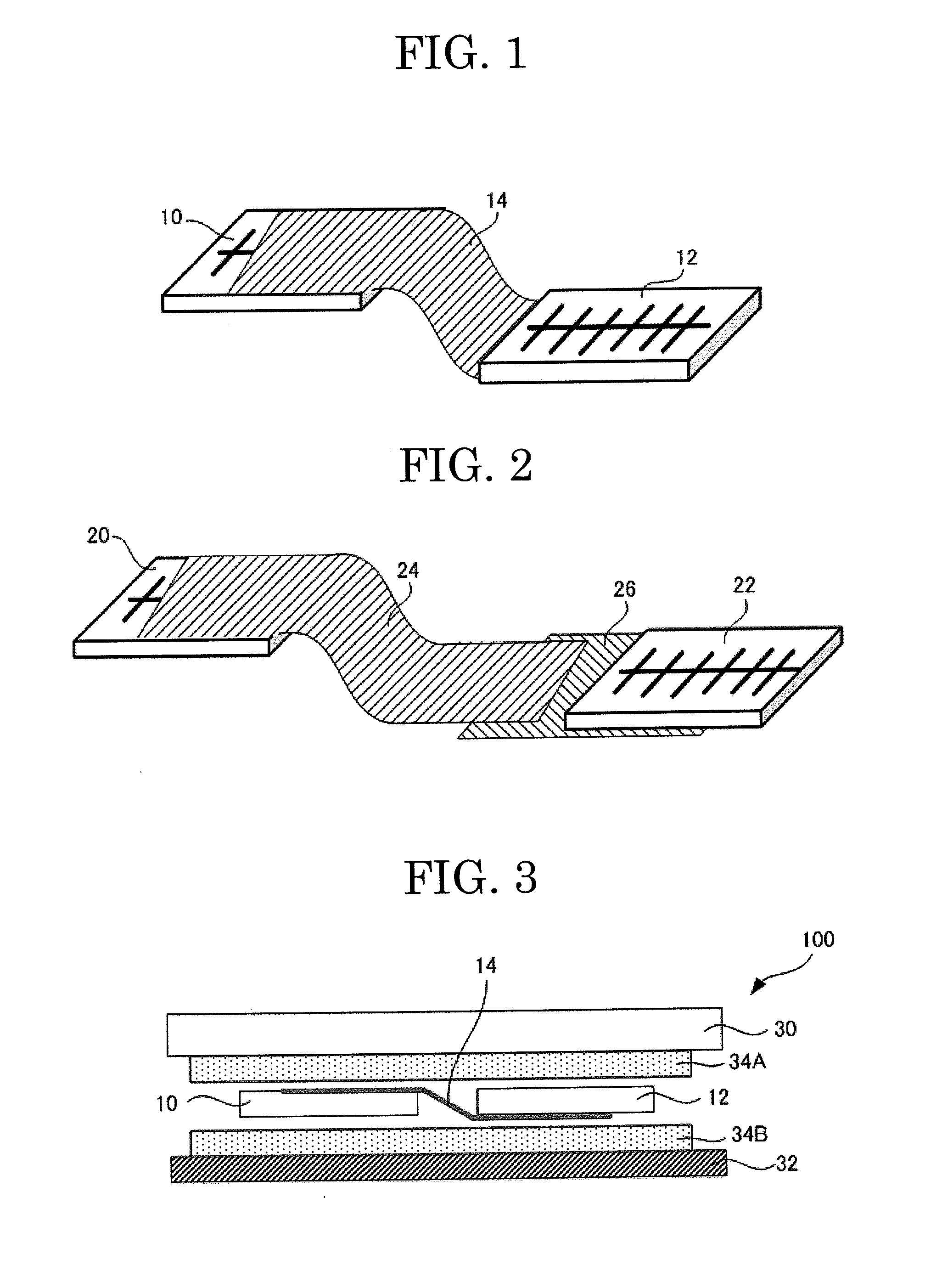
[0011]The inventors of the present invention have been intensively studied the above problems, and obtained the following findings. That is, when an interconnection of solar battery elements is achieved by bonding a transparent conductive film, the soldering step in the conventional method for producing a solar battery is not required, the cracks and warpage of the solar battery element and separation of the interconnector can be inhibited and environmental load is reduced. Thus, a solar battery having high reliability can be provided. The conversion efficiency of the solar battery can be improved by reducing light shielding ratio, and improving electrical contact ratio of electrodes of the solar battery element.
[0033]The present invention can solve the conventional problems and provide a solar battery having high conversion efficiency and reliability, and a method for producing a solar battery does not require soldering, causes less load on environment, can inhibit cracks and warpage of the solar battery element, and separation of an interconnector, thereby producing the solar battery with ease and efficiency.

Problems solved by technology

Thus, the process for producing a solar battery module is complicated and has problems, such as warpage and cracks of the silicon substrate, and electrode detachment, occurring due to heat stress upon soldering an interconnector, causing decrease in yield.
Hereafter, there is a high possibility that the silicon substrates are getting much thinner, and problems, such as the warpage and cracks of the silicon substrate, and electrode detachment due to heat stress upon soldering an interconnector, easily and more markedly occur, and these problems must be solved.
However, these techniques have not been satisfied, and further improvement is demanded.
However, it is concerned that the soldering using a lead-free soldering needs high temperature, causes problems such as warpage, cracks, and results in low strength.

Method used


Image

  • Solar battery and production method thereof
  • Solar battery and production method thereof
  • Solar battery and production method thereof

Examples


first embodiment

of Transparent Conductive Film

[0065]The transparent conductive film of the first embodiment includes at least a film substrate and a conductive layer, and further includes appropriately selected other members as necessary.

—Film Substrate—

[0066]The film substrate is suitably selected depending on the intended purpose without any restriction, but preferably has flexibility, for example, a polymer film formed of acrylic resins such as polycarbonate, polymethacrylate; vinyl chloride resins, such as polyvinyl chloride, vinyl chloride copolymer; thermoplastic resins such as polyarylate, polysulfone; polyether sulfone; polyimide; PET; PEN; fluororesin; phenoxy resins; polyolefine resins; nylon; styrene resins; and ABS resins.

—Conductive Layer—

[0067]The conductive layer is suitably selected depending on the intended purpose without any restriction. It is preferred that the conductive layer be formed of a metal mesh, or contain a binder and conductive fibers.

——Metal Mesh——

[0068]The metal mes...

second embodiment

of Transparent Conductive Film

[0111]In the second embodiment, the transparent conductive film contains at least a binder and a conductive material, and further contains appropriately selected other components as necessary.

[0112]The binder is suitably selected depending on the intended purpose without any restriction, and the same as those in the transparent conductive film of the first embodiment can be used.

[0113]The conductive material is suitably selected depending on the intended purpose without any restriction. For example, a metal mesh, conductive fibers, and the like are preferably used.

[0114]The metal mesh and the conductive fibers are suitably selected depending on the intended purpose without any restriction, and the same as those in the transparent conductive film of the first embodiment can be used.

[0115]The transparent conductive film of the second embodiment can be formed in such a manner that a transparent conductive part containing the conductive material and the bin...

production example 2

—Production of Transparent Conductive Film 102—

[0171]As a mesh formed by printing a silver paste, a metal mesh was formed on a PET film substrate having a thickness of 50 μm in accordance with the method described in Example 1 of JP-A No. 2006-24485. A screen printing mesh with line / space=195 μm / 5 μm and with a pitch of 200 μm was used for forming the metal mesh, to thereby produce a transparent conductive film 102. The obtained transparent conductive film 102 was a lattice-shaped metal mesh formed on the PET film substrate. The surface resistance of the transparent conductive film on whose surface the metal mesh was formed was 1.3 Ω / sq, and the transmittance of the film was 94% as measured in the same manner as in Production Example 1.


PUM


Abstract

A solar battery including a transparent conductive film; and a solar battery element, wherein the transparent conductive film is bonded to a surface of the solar battery element, and the transparent conductive film is electrically connected to the solar battery element.

Description

TECHNICAL FIELD[0001]The present invention relates to a solar battery containing at least a solar battery element to whose surface a transparent conductive film is bonded, and a method for producing the solar battery.BACKGROUND ART[0002]For example, a crystalline silicon solar battery is formed in such a manner that electrodes formed of silver or aluminum are formed in a pattern on a front surface and a back surface of a silicon substrate in which a p-n junction is formed, and the electrodes are connected in series via a string of copper, or the like, so-called an interconnector, to thereby form a solar battery, which is called as a module.[0003]The series connection by means of an interconnector is formed in such a manner that a solar battery element, in which electrodes are patterned on a silicon substrate in which a p-n junction is formed, is immersed in flux containing an activator, dried with warm air, and then immersed in a solder bath, to thereby coat the electrodes with a so...

Claims


Application Information

Patent Timeline
Patent Type & Authority Applications(United States)
IPC IPC(8): H01L31/05H01L31/18B82Y99/00
CPCH01B1/22H01B1/24H01L31/0512H01L31/048Y02E10/50H01L31/02008
Inventor HOSOYA, YOICHIMIYAGISHIMA, NORINAOI, KENJIKURAMACHI, TERUHIKONISHIMURA, RYOJI
Owner FUJIFILM CORP
Learn More