Anode structure for use in organic el device, production method thereof and organic el device

Active Publication Date: 2011-12-22
MITSUI MINING & SMELTING CO LTD
View PDF10 Cites 3 Cited by
  • Summary
  • Abstract
  • Description
  • Claims
  • Application Information

AI Technical Summary

Benefits of technology

[0011]The inventors have now found that it is possible to provide an anode structure which is superior in alkali resistance and can lengthen lifetime of an organic EL device as well as can ensure a high work function suitable for an anode for a high-luminance, high-power-efficient organic EL device by providing, on an anode layer made of a particular metal or alloy, a buffer layer made of an electrically conductive amorphous carbon having an extremely low hydrogen concentration. In addition, the inventors have also found that this anode structure can be used not only as an anode but also as an auxiliary wiring capable of establishing an ohmic contact with a cathode, depending on its patterning, and thus enables simultaneous formation of the anode and the auxiliary wiring so as to significantly simplify the process of producing the auxiliary wiring and the anode.
[0012]Thus, an object of the present invention is to provide an anode structure which is superior in alkali resistance and can lengthen lifetime of an organic EL device as well as can ensure a high work function suitable for an anode for a high-luminance, high-power-efficient organic EL device. In addition, another object of the present invention is to provide an anode structure which can be used not only as an anode but also as an auxiliary wiring capable of establishing an ohmic contact with a cathode, depending on its patterning, and thus to enables simultaneous formation of the anode and the auxiliary wiring so as to significantly simplify the process of producing the auxiliary wiring and the anode.

Problems solved by technology

However, the oxide buffer layer forcibly doped with oxygen causes a phenomenon in which oxygen gradually leaks out to lower the work function.
However, this technique requires many steps in that it is necessary to dope the diamond-like carbon film with impurities for providing electrical conductivity as well as to terminate the surface of the diamond-like carbon film with fluorine or the like for heightening the work function by conducting an RF plasma treatment during which a gas such as CF4 is introduced.
Moreover, the diamond-like carbon film produced by this technique contains impurities or the like at a meaningful level, raising a concern with negative effects such that the impurities are diffused into the organic EL layer which is in direct contact with the diamond-like carbon film.

Method used


Image

  • Anode structure for use in organic el device, production method thereof and organic el device
  • Anode structure for use in organic el device, production method thereof and organic el device
  • Anode structure for use in organic el device, production method thereof and organic el device

Examples


example 1

Preparation and Evaluation of Anode Structure

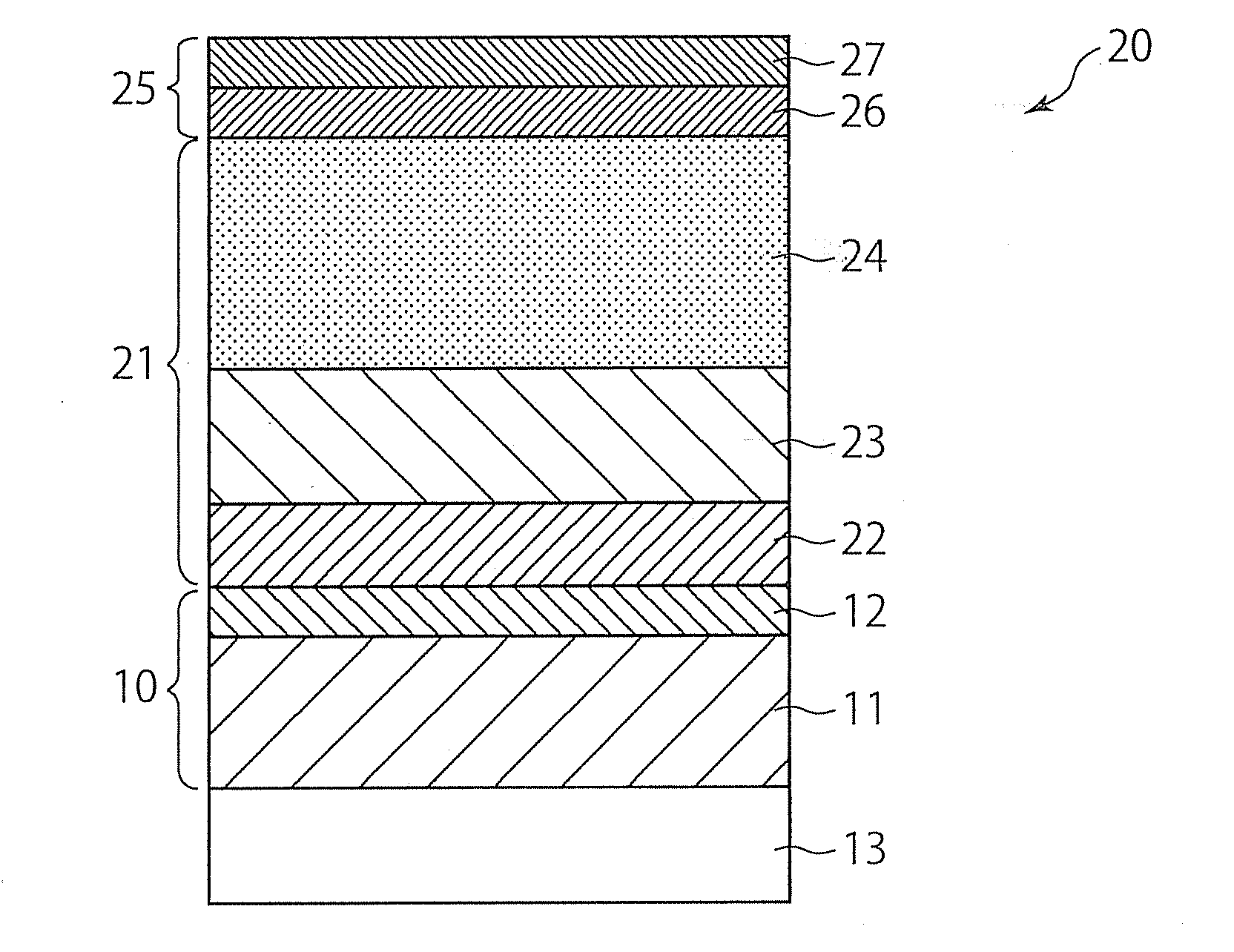
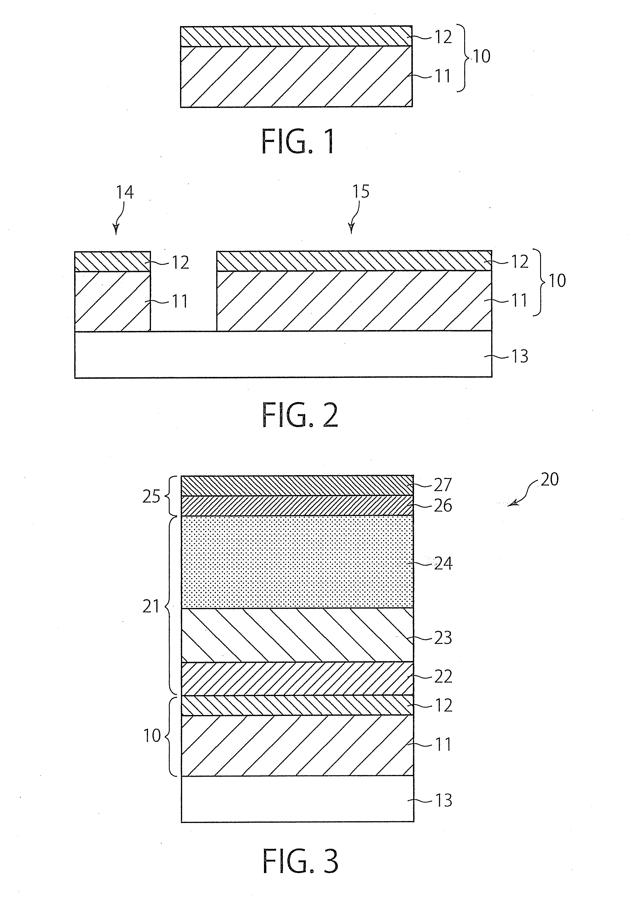
[0056]Alkali-free glass (Corning #1737) was prepared as a substrate. An aluminum film with a thickness of 150 nm was formed on the substrate by sputtering. After an aluminum target (ACX manufactured by Mitsui Mining and Smelting Co., Ltd., 203 mm diameter×8 mm thickness) was placed in a multi-chamber-type magnetron sputtering apparatus (MSL-464, Tokki Corporation) connected to a cryopump, this sputtering was conducted under the conditions of an input power (DC) of 1000 W; an ultimate vacuum of 5×10⁻⁵ Pa; a sputtering pressure of 0.5 Pa; an Ar flow rate of 100 sccm; and a substrate temperature of room temperature. Thus, an anode layer made of aluminum was formed.

[0057]An electrically conductive amorphous carbon film as a buffer layer was formed on the anode layer by sputtering. After a graphite target (1G-70 manufactured by Toyo Tanso Co., Ltd., 203.2 mm diameter×8 mm thickness) prepared by sintering graphite powder was placed in a multi-c...

example 2

Influence of Presence / Absence of Electrically Conductive Amorphous Carbon Buffer Layer on Properties

[0065]In order to investigate influence of presence / absence of the electrically conductive amorphous carbon buffer layer on properties, an ITO film was used as an anode layer to prepare an organic EL device with a structure shown in FIG. 7 in which an electrically conductive amorphous carbon buffer layer was formed on the anode layer. The reason why light-transmissive ITO film was used as an anode layer instead of a reflective film such as Al film was to conduct the experiment easily in a simplified manner, not to mention that the evaluation result of the electrically conductive amorphous carbon buffer layer in this example is also applicable to the present invention directed to a top-emission type organic EL device. Specifically, an organic EL device 50 shown in FIG. 7 has a laminated structure in which, on a glass substrate 51, an ITO anode layer 52, an electrically conductive amorp...


PUM

PropertyMeasurementUnit
Thicknessaaaaaaaaaa
Thicknessaaaaaaaaaa
Volumeaaaaaaaaaa

Abstract

The present invention relates to an anode structure for use in a top-emission type organic EL device which comprises a laminated structure comprising an anode layer made of at least one selected from the group consisting of aluminum, aluminum alloys, silver and silver alloys; and a buffer layer directly provided on the anode layer and made of an electrically conductive amorphous carbon having a hydrogen concentration of 15 at. % or less. According to the present invention, there is provided an anode structure which is superior in alkali resistance and can lengthen lifetime of an organic EL device as well as can ensure a high work function suitable for an anode for a high-luminance, high-power-efficient organic EL device.

Description

CROSS-REFERENCE TO RELATED APPLICATION[0001]This application claims priority to Japanese Patent Application No. 2009-184985 filed on Aug. 7, 2009, the entire content of which is incorporated herein by reference.TECHNICAL FIELD[0002]The present invention relates to an anode structure for use in a top-emission type organic EL device, a production method thereof, and an organic EL device.BACKGROUND ART[0003]In recent years, organic EL (electroluminescence) devices have been drawing attention as display devices such as mobile phone display panels or flat-screen televisions. In particular, top-emission type organic EL devices, in which light is emitted from the side opposite to a driving circuit board, are suitable for achieving high luminance and high definition, because the top-emission type devices can ensure a high aperture ratio with no restriction by light-blocking objects such as TFT (Thin Film Transistor) and a wiring, as compared with bottom-emission type organic EL devices, in ...

Claims


Application Information

Patent Timeline
IPC IPC(8): H01L51/52H01J9/02H01J1/00C23C14/14C23C14/34
CPCH01L51/5218H05B33/26H01L2251/5315H10K85/20H10K2102/3026H10K59/80518H10K50/818
Inventor MATSUURA, YOSHINORIKAWAI, NOBUYUKIKUBOTA, TAKASHI
Owner MITSUI MINING & SMELTING CO LTD
Why Eureka
Try Eureka