Electrohydrodynamic device with flow heated ozone reducing material

Inactive Publication Date: 2011-12-22
PANASONIC PRECISION DEVICES
View PDF2 Cites 12 Cited by
  • Summary
  • Abstract
  • Description
  • Claims
  • Application Information

AI Technical Summary

Benefits of technology

[0012]It has been discovered that ozone produced by EHD systems may be broken down or otherwise reduced or sequestered by provision of ozone reducing materials downstream from one or more of primary heat transfer surfaces. It particular, it has been discovered that use of a screen, grate, grid network, or other mesh-like material (sometimes referred to herein as simply “mesh”) having a short characteristic length can provide a large amount of surface area with reduced boundary layer conditions and that heating of the ozone reducing material on the mesh by air heated upstream by the primary heat transfer surfaces serves to substantially enhance the efficacy of the ozone reducing material. Accordingly, provision of ozone reducing materials on or in the form of a mesh can provide desirable reductions in ozone levels, particularly when the ozone reducing materials are heated, e.g., by warmer air coming off of primary heat transfer surfaces upstream.
[0035]Advantages of use of an EHD device for thermal management in such devices includes substantially silent operation, reduced power consumption, reduced vibration, reduced thermal solution footprint and volume, and form factor flexibility, e.g., capability to utilize space around other electronics.

Problems solved by technology

Elevated ozone levels have been associated with respiratory irritation and certain health issues.

Method used


Image

  • Electrohydrodynamic device with flow heated ozone reducing material
  • Electrohydrodynamic device with flow heated ozone reducing material
  • Electrohydrodynamic device with flow heated ozone reducing material

Examples


Embodiment Construction

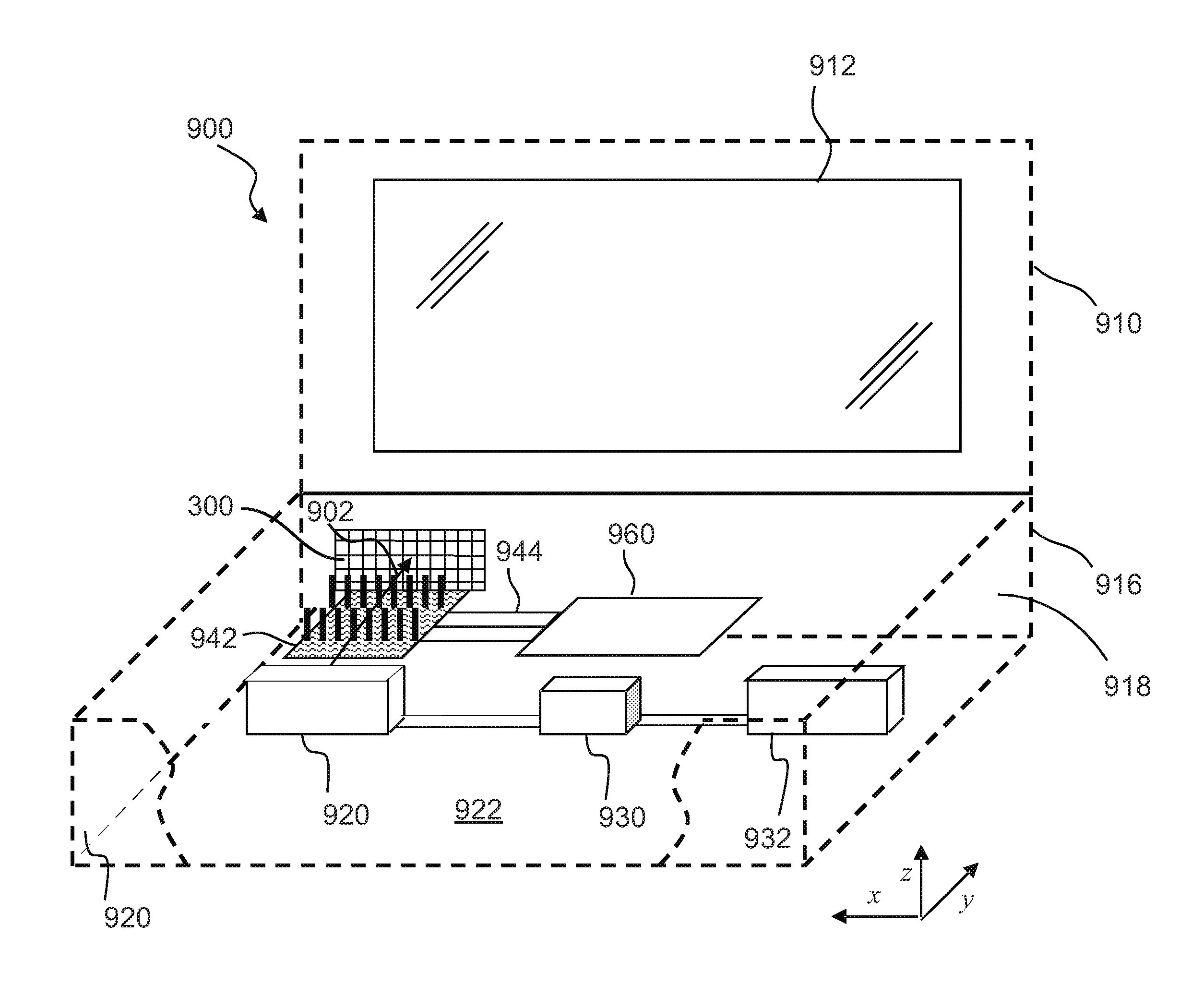
[0048]Some implementations of thermal management systems described herein employ EHD devices to motivate flow of a fluid, typically air, based on acceleration of ions generated as a result of corona discharge. Other implementations may employ other ion generation and motivation techniques and will nonetheless be understood in the descriptive context provided herein. For example, in some implementations, techniques such as silent discharge, AC discharge, dielectric barrier discharge (DBD) or the like may be to generate ions that are in turn accelerated in the presence of electrical fields to motivate fluid flow.

[0049]Typically, when a thermal management system is integrated into an operational environment, heat transfer paths (often implemented as heat pipes or using other technologies) are provided to transfer heat from where it is generated or dissipated to a location(s) within an enclosure where air flow motivated by an EHD device(s) flows over primary heat transfer surfaces. For ...


PUM

PropertyMeasurementUnit
Fractionaaaaaaaaaa
Thicknessaaaaaaaaaa
Thicknessaaaaaaaaaa

Abstract

A thermal management apparatus includes an electrohydrodynamic fluid accelerator energizable to motivate fluid flow. Primary heat transfer surfaces are positioned to transfer heat into the fluid flow and an ozone reducing material is positioned downstream of the primary heat transfer surfaces. Heating of the ozone reducing material by the fluid flow increases the efficacy of the ozone reducing material. A method of making a product includes positioning an emitter electrode and at least one other electrode to motivate fluid flow along a flow path when the electrodes are energized. The method further includes positioning heat transfer surfaces in the flow path to transfer heat to the fluid flow and positioning ozone reducing material downstream of the heat transfer surfaces in the flow path, the ozone reducing material selected such that heating of the ozone reducing material by the fluid flow increases ozone reducing efficacy of the ozone reducing material.

Description

BACKGROUND[0001]1. Field of the Invention[0002]The present application relates to thermal management, and more particularly, to micro-scale cooling devices that use electrohydrodynamic (EHD, also known as electro-fluid-dynamic, EFD) technology to generate ions and electrical fields to control the movement of fluids, such as air, as part of a thermal management solution to dissipate heat.[0003]2. Description of the Related Art[0004]Devices built using the principle of the ionic movement of a fluid are variously referred to in the literature as ionic wind machines, electric wind machines, corona wind pumps, electro-fluid-dynamics (EFD) devices, electrohydrodynamic (EHD) thrusters and EHD gas pumps. Some aspects of the technology have also been exploited in devices referred to as electrostatic air cleaners or electrostatic precipitators.[0005]In general, EHD technology uses ion flow principles to move fluids (e.g., air molecules). Basic principles of EHD fluid flow are reasonably well ...

Claims


Application Information

Patent Timeline
IPC IPC(8): F28D21/00H02K15/00H02K44/02
CPCF04B17/00F04B19/006Y10T29/49009F28F13/16F04B37/10
Inventor HONER, KENNETH
Owner PANASONIC PRECISION DEVICES
Why Eureka
Try Eureka