Rolling mill temperature control

a technology of rolling mills and temperature control, which is applied in the direction of rolling mill control devices, metal rolling, work treatment devices, etc., can solve the problems of spoiling the appearance of the rolling process, difficult to ensure, and large heat generated by the rolling process

Active Publication Date: 2011-12-22
PRIMETALS TECH
View PDF5 Cites 8 Cited by
  • Summary
  • Abstract
  • Description
  • Claims
  • Application Information

AI Technical Summary

Benefits of technology

According to a further embodiment, lubricant supply can be arranged to direct lubricant at less that 10 litre/minute. According to a further embodiment, the plurality of cryogenic fluid applicators can be arranged to direct the cryogenic fluid to one or more of a plurality of zones in the arc region of at least one of the rolls. According to a further embodiment, an apparatus may further comprise at least one barrier arranged to prevent intrusion by the cryogenic fluid to the wedge region of the roll and, or the strip. According to a further embodiment, the barrier may comprise a solid barrier. According to a further embodiment, the barrier may comprise a gas curtain. According to a further embodiment, an apparatus may further comprise an inner compartment enclosing the rolls; an outer compartment enclosing the inner compartment; means for maintaining the inner compartment at a positive pressure relative to ambient pressure and means for m...

Problems solved by technology

However, even with lubrication, the rolling process generates a large amount of heat, which must be dissipated to prevent equipment overheating and the breakdown of the lubricant.
However, unless the water is completely removed from the strip immediately after rolling, stains are created on the strip surface, spoiling its appearance.
In practise, it has been very difficult to ensure completely dry strip unless the strip exit temperature from the mill is considerably greater than 100° C. This limits the practicality of rolling and hence just a few specialist mills rolling specific products use this method.
However, kerosene is not the best lubricant or coolant and has significant fire safety, environmental and health problems associated with it.
Such volumes require expensive recirculation and filtration systems and will inevitably cause oil mist to form which requires expensive fume extraction and cleaning systems.
One of the main challenges in the cold rolling of aluminium strip and foil is to ens...

Method used


Image

  • Rolling mill temperature control
  • Rolling mill temperature control
  • Rolling mill temperature control

Examples


Embodiment Construction

In the context of this specification, the term cryogen refers to a substance which is normally gaseous at room temperature but which is maintained in liquid state by suitable control of temperature and pressure and which is used as a coolant. Related terms such as cryogenic should be construed accordingly.

Cryogen includes, but is not limited to nitrogen, carbon dioxide, argon and oxygen.

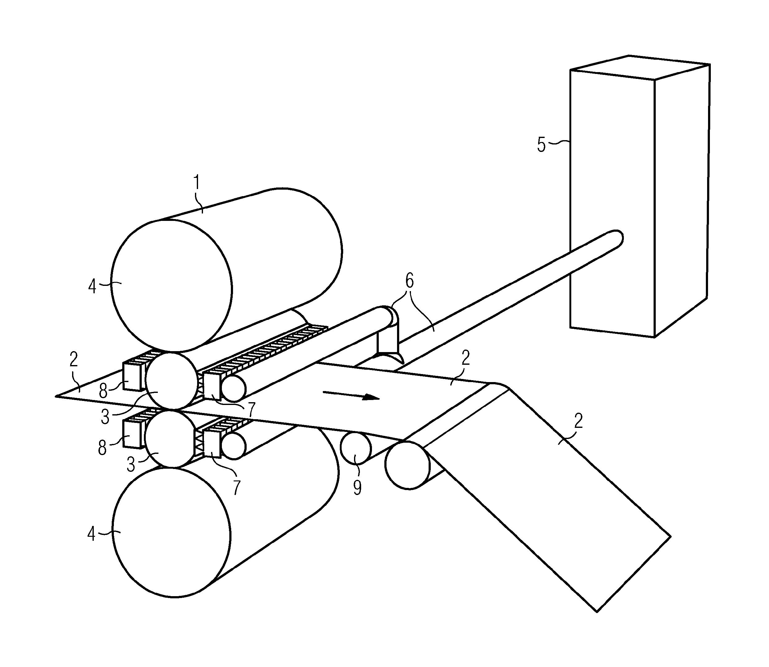
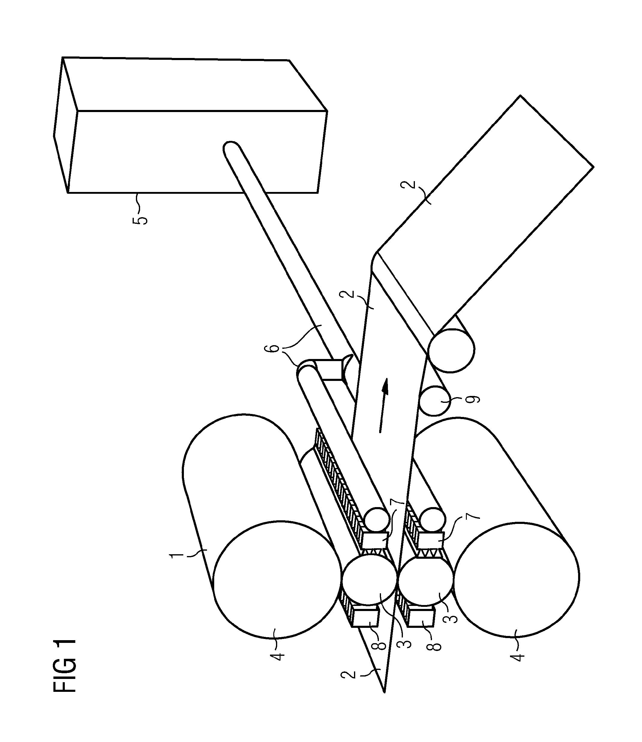
Embodiments offer a new improved cooling and flatness control technology to be conceived with the following features:Banks of cryogenic gas or liquid applicators apply cooling to either or both sides of the mill rollsThese applicators are divided into individually controllable zones which can be controlled to give a varying cooling effect across the width of the rollAdditionally, one or more full width roll heating devices are used in conjunction with the roll coolant applicators.The roll heating devices are split into a number of individually controllable zones across the width of the roll. The numb...


PUM

PropertyMeasurementUnit
Pressureaaaaaaaaaa
Sizeaaaaaaaaaa
Widthaaaaaaaaaa

Abstract

For controlling the flatness of the strip during the rolling of aluminium strip or foil, the system consists of a full width bank of cryogenic roll cooling devices acting on the roll(s) and a full width bank of roll heating devices also acting the roll(s). Both or either of the cooling and heating banks are divided into individually controllable zones. A process automation system controls the action of the cooling and heating banks via feedback from a strip shape meter and/or a predictive process model, in order, by thermal growth/contraction, to create the best roll profile for rolling flat strip.

Description

TECHNICAL FIELDThe invention relates to the field of aluminium strip or foil rolling mills and describes a new process which will improve the temperature control of the mill rolls, in order to improve strip flatness and give other safety and production benefits.BACKGROUNDThe process of rolling aluminium requires lubrication in order to gain a satisfactory surface finish of the strip at higher reductions. However, even with lubrication, the rolling process generates a large amount of heat, which must be dissipated to prevent equipment overheating and the breakdown of the lubricant. Therefore additional cooling of the rolls is required. At present this has only been achieved in two ways:A small number of mills rolling cold aluminium strip or foil use water based emulsions as the rolling coolant and lubricant. This would seem to be an ideal solution as water has a high cooling capacity, whilst the oil content can be tuned to give good lubrication properties. However, unless the water i...

Claims


Application Information

Patent Timeline
IPC IPC(8): B21B3/00B21B38/02B21B27/10B21B37/32
CPCB21B3/00B21B9/00B21B15/005B21B27/10B21B27/106B21B2027/103B21B37/74B21B38/00B21B38/02B21B2003/001B21B37/32
Inventor MCRAE, ALAN DOUGLASOSBORNE, PAUL RONALDSMITH, PETER DERRICK
Owner PRIMETALS TECH
Why Eureka
Try Eureka