Turbine blade nested seal damper assembly

a technology of nested seals and dampers, which is applied in the direction of machines/engines, transportation and packaging, liquid fuel engines, etc., can solve the problems of inflexible seal materials, designed to operate for extended durations, and material properties of seals and dampers compromised

Active Publication Date: 2006-10-17
RTX CORP
View PDF16 Cites 65 Cited by
  • Summary
  • Abstract
  • Description
  • Claims
  • Application Information

AI Technical Summary

Benefits of technology

[0010]The damper-seal assembly includes the seal that prevents hot gases from penetrating a gap between adjacent turbine blades. The seal abuts the inner surface of the platform and bridges the gap to block the flow of hot gases. The damper includes a recess within which the seal nests. On each side of the recess the damper includes a surface that contacts the inner most surfaces of the turbine blade. The surface of the damper provides frictional contact that absorbs vibrational energy from the turbine blade generated during operation.
[0012]The damper-seal assembly of this invention provides for the use of separate material for the seal and the damper while providing for optimal placement of both the seal and the damper. The seal includes a plastically deformable material that provides the desired seal to prevent the intrusion of hot gases and the damper provides the dense rigid structure necessary for absorbing vibrational energy generated during operation.

Problems solved by technology

Problems arise when hot gases penetrate below the platform of the turbine blades.
This is done because components below the platform are generally not designed to operate for extended durations at the elevated temperatures of the hot gases.
However, the material properties of the seal and the damper are compromised to accommodate the separate functions.
That is the seal material is not as flexible as desired in order to provide the dampening properties required and the damper material does not provide the most beneficial dampening properties in order to provide some flexibility for the seal.
The compromise between favorable dampening properties and favorable seal properties yields less than desirable performance for both functions.

Method used


Image

  • Turbine blade nested seal damper assembly
  • Turbine blade nested seal damper assembly
  • Turbine blade nested seal damper assembly

Examples


Embodiment Construction

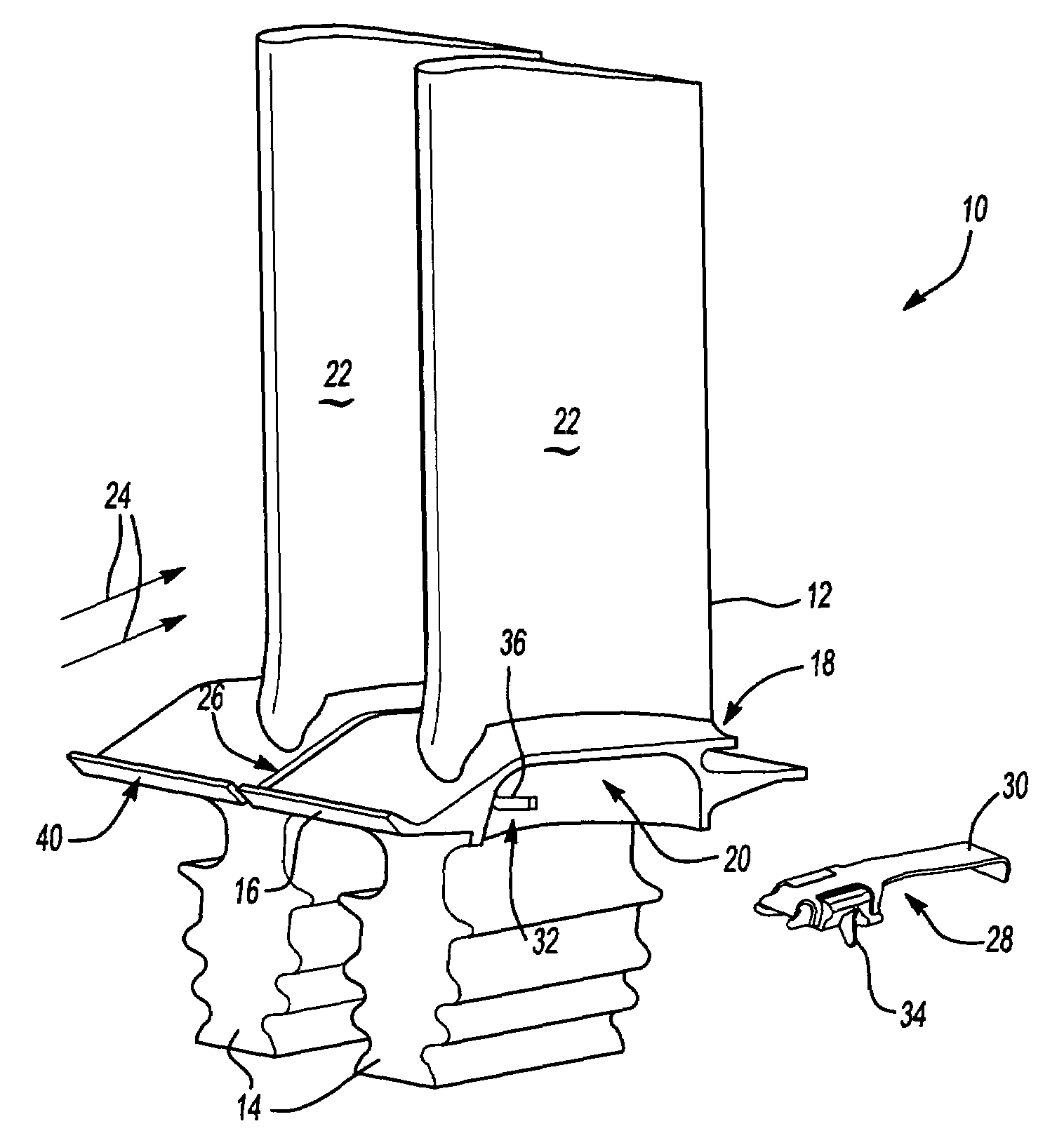
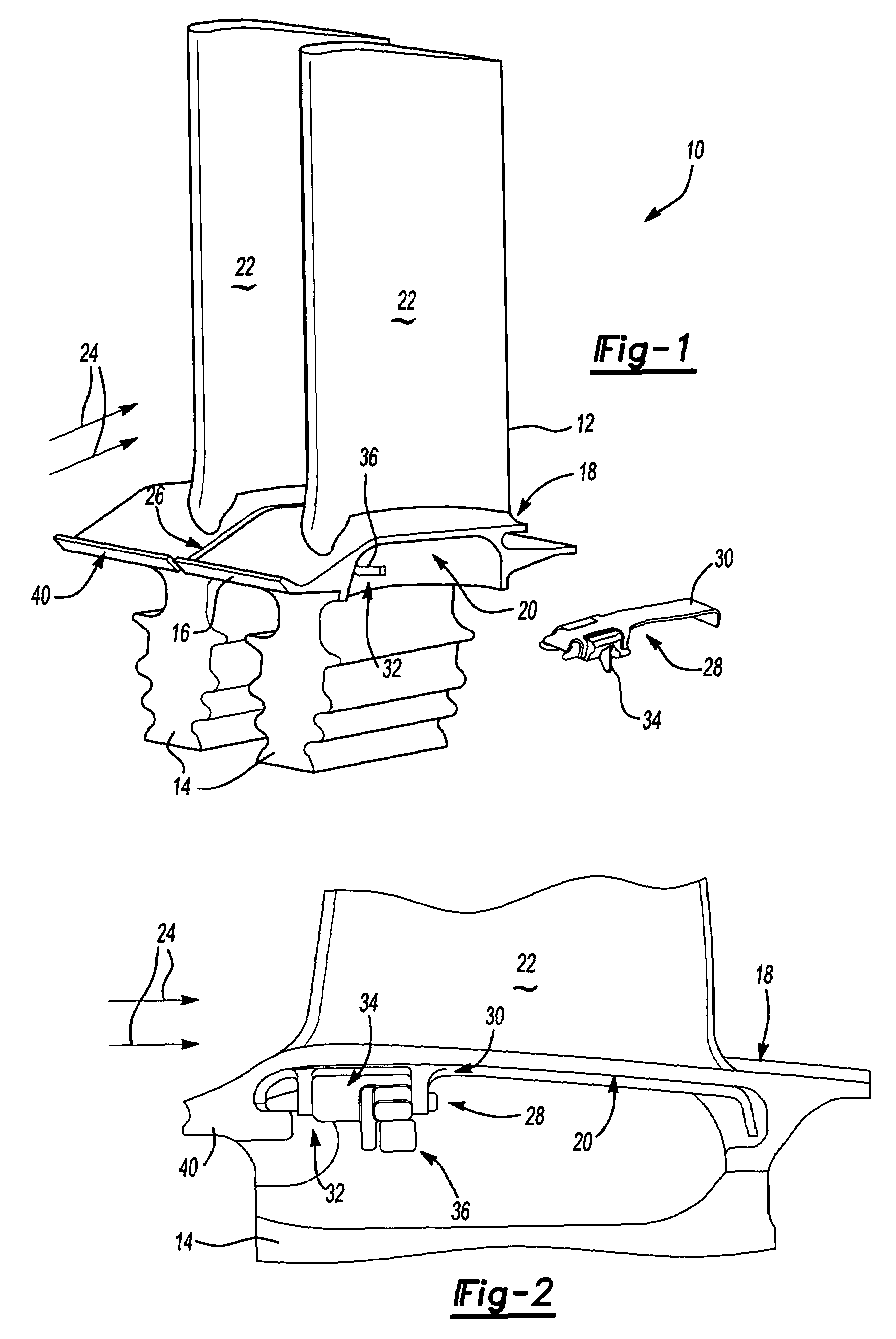
[0020]Referring to FIG. 1, a turbine assembly 10 includes a plurality of adjacent turbine blades 12. Each of the turbine blades 12 includes a root 14 that is fit into a radial slot of a turbine rotor (not shown). Radially outward of the root 14 is a platform 16. The platform 16 includes an outer surface 18 and an inner surface 20. The inner surface 20 is disposed radially inward of the outer surface 18. An airfoil 22 extends upward from the platform 16.

[0021]Hot gas 24 flows around the airfoil 22 and over the outer surface 18. A gap 26 extends axially between adjacent turbine blades 12. The gap 26 prevents contact between the turbine blades 12. A damper-seal assembly 28 includes a seal 30 that prevents hot gases 24 from penetrating the gap 26 and penetrating the underside of the platform 16. The seal 30 is positioned within a cavity 32 formed between adjacent turbine blades 12. The seal 30 abuts the inner surface 20 of the platform 16 and bridges the gap 26 to block the flow of hot ...


PUM


Abstract

A turbine blade damper seal assembly includes a seal and a damper that both abut a radially outermost non-gas path surface. The seal is fabricated from a plastically deformable material and nests within a recess of the damper. The damper is fabricated from a rigid material that absorbs vibrational energy generated during operation. The recess within the damper provides for both the damper and the seal to be positioned at the radially outermost non-gas path surface.

Description

[0001]The US Government may have certain rights in this invention in accordance with Contract Number N00019-02-C-3003 awarded by the United States Navy.BACKGROUND OF THE INVENTION[0002]This application relates generally to a turbine seal and damper assembly and specifically to a nested seal and damper assembly.[0003]Conventional gas turbine engines include a turbine assembly that has a plurality of turbine blades attached about a circumference of a turbine rotor. Each of the turbine blades is spaced a distance apart from adjacent turbine blades to accommodate movement and expansion during operation. The blades typically include a root that attaches to the rotor, a platform and a blade that extends radially outwardly from the platform.[0004]Problems arise when hot gases penetrate below the platform of the turbine blades. Hot gases flowing over the platform are prevented from leaking between adjacent turbine blades by a seal. This is done because components below the platform are gene...

Claims


Application Information

Patent Timeline
Patent Type & Authority Patents(United States)
IPC IPC(8): F01D5/26F01D25/04F01DF01D5/10F01D11/00F01D25/06
CPCF01D5/10F01D5/22F01D11/006F01D11/008F01D25/06F01D5/00F01D5/12F01D5/16
Inventor BEATTIE, JEFFREY
Owner RTX CORP
Why Eureka
Try Eureka