
Complex apparatus and method for polishing an ingot block

a technology of ingot block and complex apparatus, which is applied in the direction of grinding machine components, grinding feeders, manufacturing tools, etc., can solve the problems of more difficult chamfering, and achieve the effect of extending the useful life of cup wheel grinding grindstones and small footprints

Inactive Publication Date: 2011-12-15
OKAMOTO MACHINE TOOL WORKS LTD
View PDF21 Cites 19 Cited by
  • Summary
  • Abstract
  • Description
  • Claims
  • Application Information

AI Technical Summary

Benefits of technology

[0035]With a throughput processing time of 40-45 minutes, the compound chamfering device described in patent reference 14 can chamfer a prism-shaped monocrystalline silicon ingot whose side is 156 mm, whose height is 250 mm, and which is cut with a band saw leaving a round part on the four corners, and it can process with high productivity an ingot block having an extreme degree of smoothness, in which the surface smoothness Ry is 0.2-0.5 μm. Also, because it has a side-peeloff processing stage 90 with a slicer, there is the advantage that during slack times in the production of semiconductor substrates, it can process left-over cylindrical silicon ingot blocks into prism-shaped silicon ingot blocks for solar cell substrates.
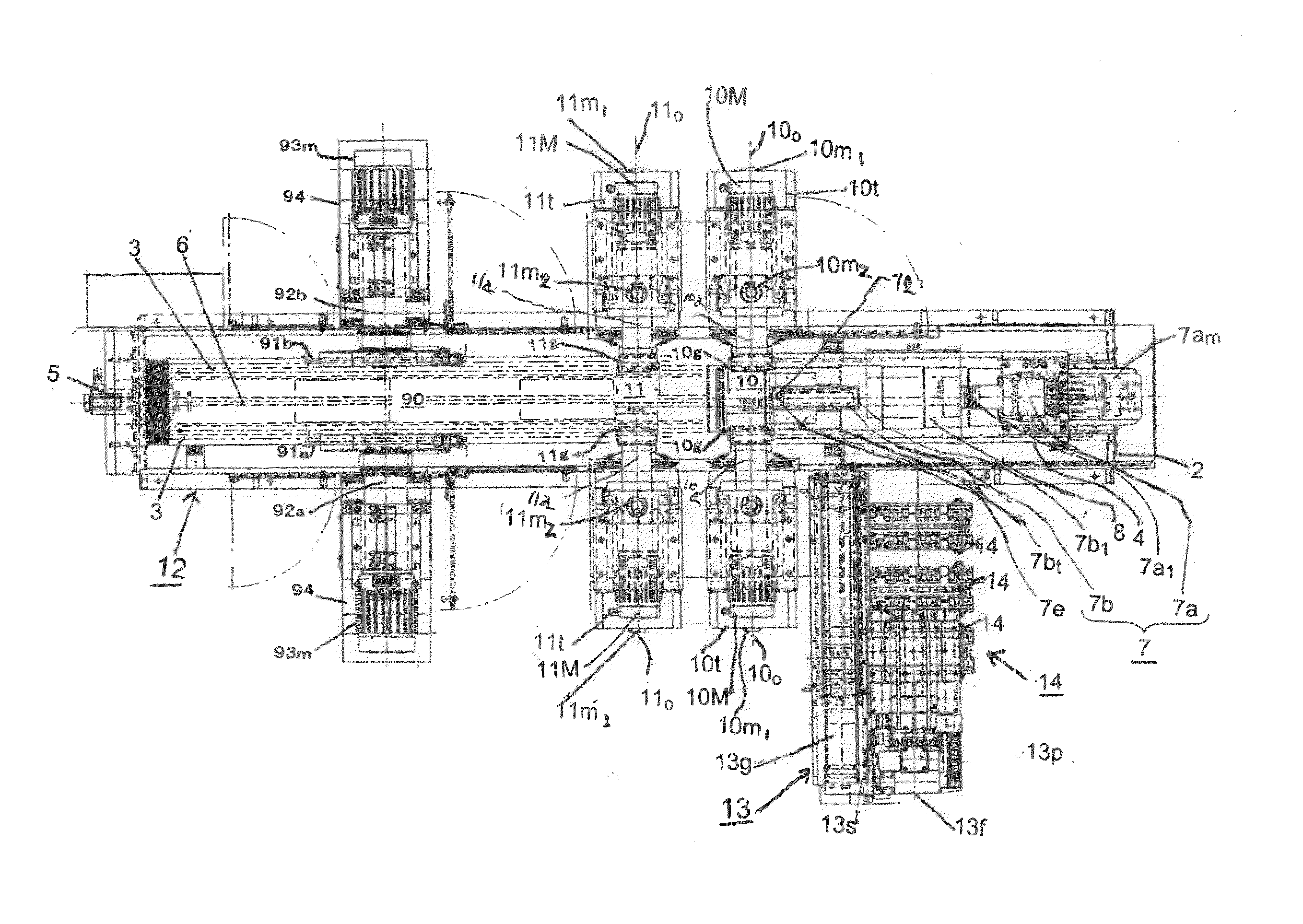
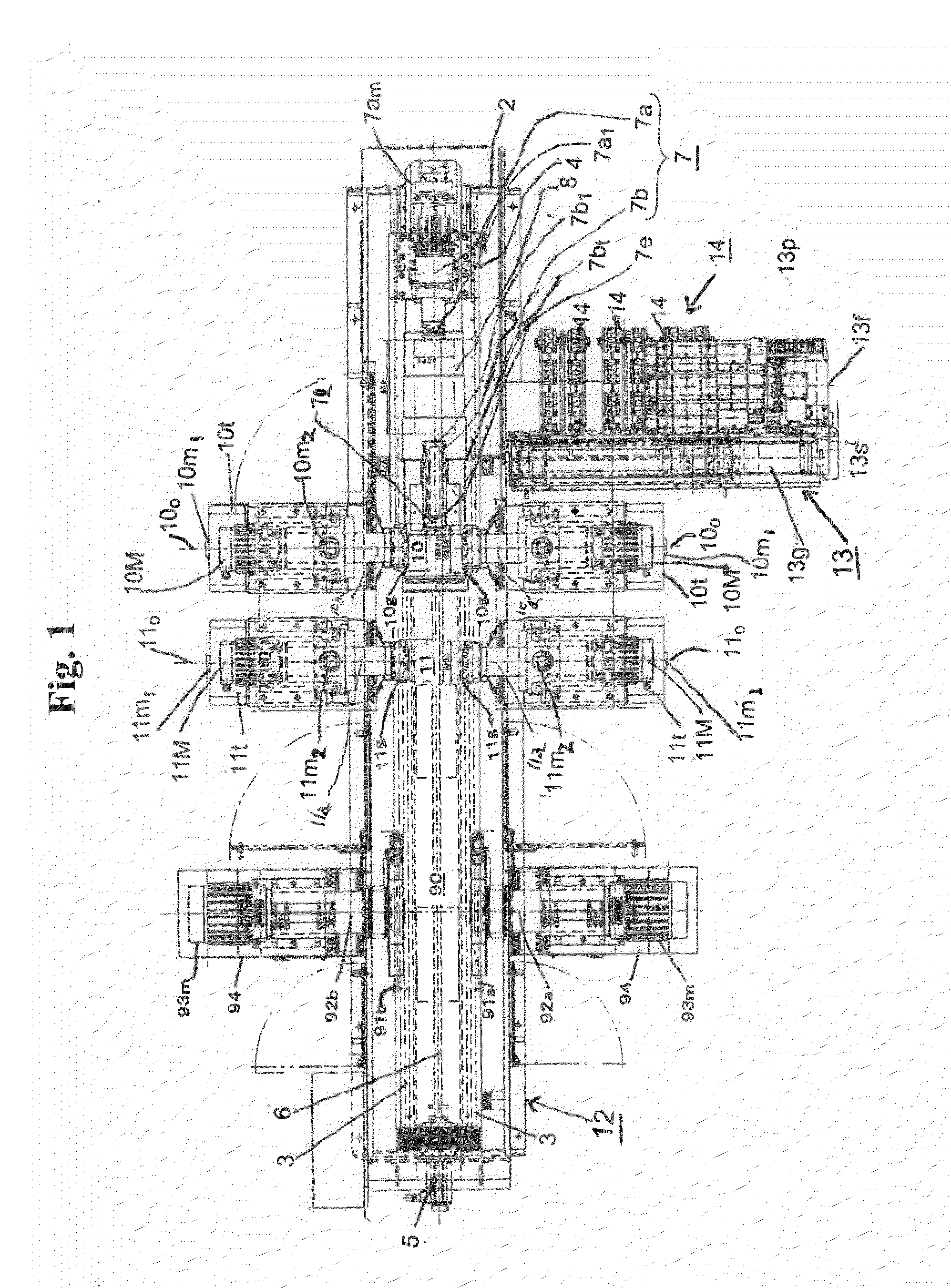
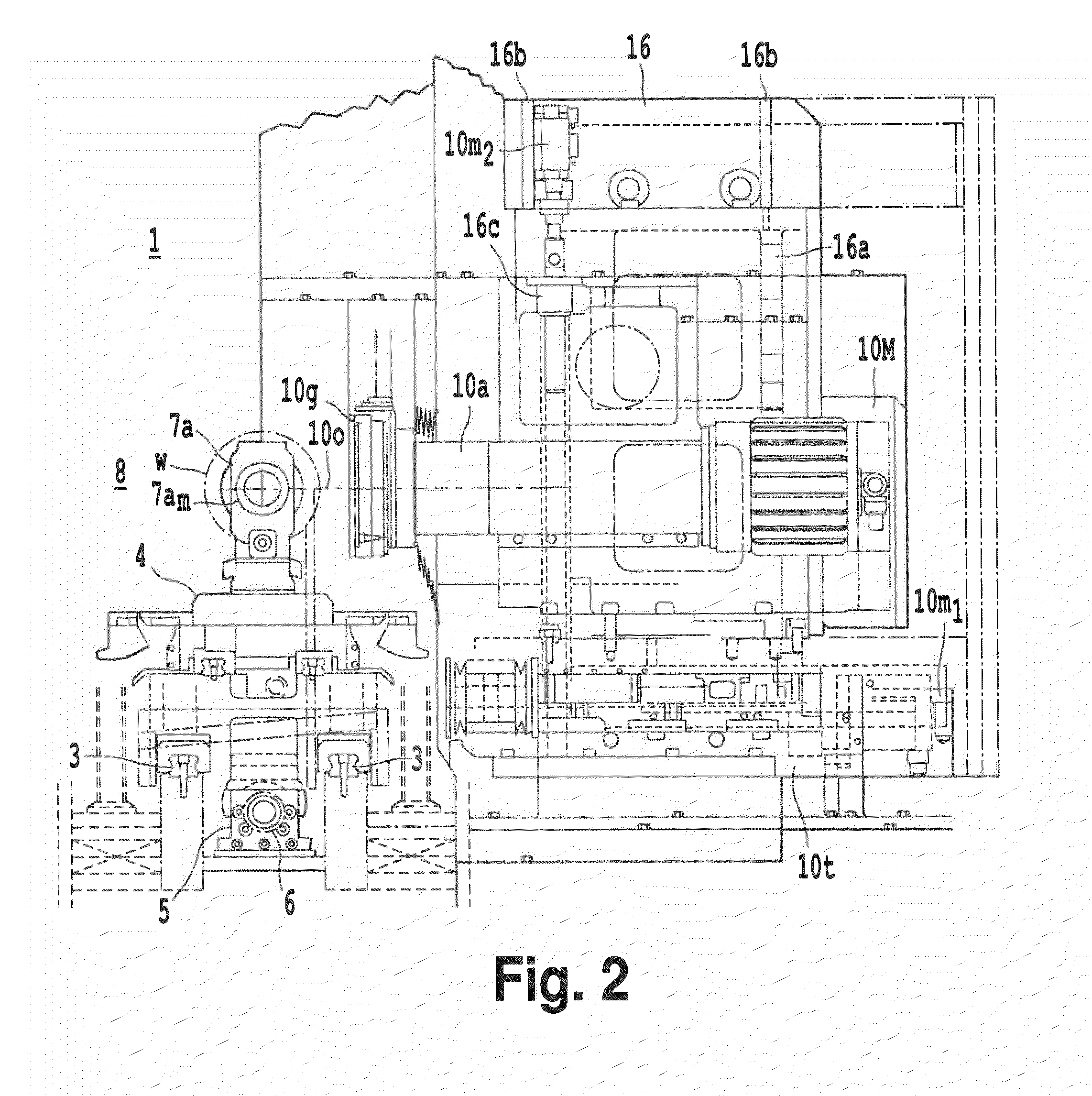
[0037]The inventors of the present invention have decided, in the compound chamfering device 1 described in the above patent reference 14, to have e) a rough grinding stage in which a pair of cup wheel type grindstones axially supported on a pair of grindstone shafts that can move forward and backward and can be raised and lowered are provided at the front and back of the workpiece table, with the workpiece table between them, in such a way that the grindstone planes face each other, and f) a finishing grinding stage in which a pair of cup wheel type grindstones axially supported on a pair of grindstone shafts that can move forward and backward and can be raised and lowered are provided at the front and back of the workpiece table, with the workpiece table between them, in such a way that the grindstone planes face each other. The rough grinding stage is used for chamfering of the four-corner round corner parts of the silicon ingot and for chamfering of the four sides. The finishing grinding stage is used for chamfering of the four-corner round corner parts of the silicon ingot and for chamfering of the four sides. The inventors of the present invention have deduced that by eliminating the round corner part finishing grinding stage with a grindstone wheel, the footprint of the compound chamfering device can be made smaller and the ingot chamfering processing time can be shortened.
[0039]The first objective of the present invention is to provide a compound chamfering device that can do grinding of the four-corners to round corner parts of a prism-shaped ingot block and surface grinding of the four sides in less time than with the compound chamfering device of the above patent reference 14.
[0044]The ingot block compound chamfering device of the invention of claim 1 can eliminate the ingot block four-corner round corner part grinding stage with a grindstone wheel, and can therefore be made with a smaller footprint (installation area) than the compound chamfering device described in patent reference 14. Also, by adopting the chamfering method described in claim 2, the useful lifetime of a cup wheel type grinding grindstone can be extended 1.5- to 2-fold. In addition, it can chamfer a prism-shaped silicon ingot block of side 156 mm and height 250 mm in 27-38 minutes, which is a shorter time than the 40-45 minutes for the compound chamfering device described in patent reference 14. Also, for its throughput processing time for chamfering a prism-shaped silicon ingot of side 156 mm and height 500 mm, this can be done in 78-82 minutes. Moreover, the surface smoothness Ry of the four side faces of a chamfered ingot block is 0.5-2 μm, which is a considerably better value than the 5 μm given in the working example described in patent reference 3.

Problems solved by technology

A monocrystalline silicon substrate has a greater photoconversion efficiency than a polycrystalline silicon substrate, but is more difficult to chamfer.

Method used


Image

  • Complex apparatus and method for polishing an ingot block
  • Complex apparatus and method for polishing an ingot block
  • Complex apparatus and method for polishing an ingot block

Examples


working examples

[0075]Using the ingot block compound chamfering device 1 of the present invention, as a workpiece w a cylindrical ingot block whose both ends are cut off in a plane is given side-peeloff and chamfering processing, making it into a prism-shaped silicon ingot block with arcs of length 5-30 mm left on the four corners.

[0076]1) Using the workpiece loading / unloading device 13, one ingot block (workpiece) stored in a workpiece stocker 14 V-shaped shelf tier is conveyed to the clamping mechanism that is in the position of the load port 8, then the workpiece is supported by the head stock 7a and tail stock 7b of the clamping mechanism 7.

[0077]2) The workpiece table 4, on which is mounted the clamping mechanism 7 that supports the ingot block suspended in the air, is moved to the left at a speed of 1-15 mm / min. The front and back end faces of the workpiece are brought into contact with a pair of rotary blades 91a, 91b, and with these rotary blades, side-peeloff processing is done, in which t...


PUM


Abstract

A compound chamfering device that manufactures prism-shaped ingot blocks of excellent surface smoothness is disclosed. The four-corner round surfaces and the four sides of a prism-shaped ingot obtained by using a pair of rotary blades of a slicer to perform four-side peeloff of a cylindrical ingot block are chamfered by rough grinding with a pair of cup wheel type rough grinding grindstones. A pair of cup wheel type finishing grinding grindstones are used to chamfering by finishing grinding the four-corner round surfaces and the four sides of the block.

Description

BACKGROUND OF THE INVENTION[0001]1. Field of the Invention[0002]The present invention concerns a compound chamfering device that can chamfer the side or circumferential surface of a prism-shaped polycrystalline silicon ingot block or monocrystalline silicon ingot block of a raw material of a square or rectangular substrate to be used as the substrate of a solar cell (solar light-emitting electric panel). It also concerns a method for using this compound chamfering device to manufacture a smooth-surface ingot silicon ingot block by chamfering the four corners or the four side surfaces of an ingot block whose C-axis end faces are cut off. When the manufactured smooth-surface ingot silicon ingot block is sliced with a wire-cut saw to a thickness of 200-240 μm to simultaneously obtain many solar-cell silicon substrates, chipping or cracking will not occur in the resulting silicon substrate.[0003]2. Description of the Related Art[0004]In the process of manufacturing a solar-cell silicon ...

Claims


Application Information

Patent Timeline
IPC IPC(8): B24B1/00
CPCB24B1/00B24B7/02B24B7/22B24B41/005B24B27/0023B24B27/0076B24B9/06
Inventor YOSHIDA, YUTAKAKOBAYASHI, KAZUOTOSHIDA, TSUYOSHIUEHARA, YUKIOTERAKUBO, YASUHIROSAITOU, HIROTSUGU
Owner OKAMOTO MACHINE TOOL WORKS LTD
Learn More