
Data processing device and method

a data processing and data technology, applied in the field of data processing devices, can solve the problems of trace buffer overflow, and insufficient bandwidth allocated for trace outputting compared to the bandwidth required, so as to reduce the overhead of trace data obtained, the effect of further reducing overhead

Inactive Publication Date: 2011-11-24
PANASONIC CORP
View PDF3 Cites 17 Cited by
  • Summary
  • Abstract
  • Description
  • Claims
  • Application Information

AI Technical Summary

Benefits of technology

[0011]The present invention has as an object to obtain the correlation between time information items of different trace data sources, while avoiding the negative effects caused by outputting even a reference timestamp in addition to local time information.
[0017]Conventionally, time information items such as a local timestamp and a reference time stamp are outputted. However, according to the present invention, only timestamp information items according to a single reference clock are outputted. This reduces the overhead of the trace data obtained at the end.
[0018]In addition, although, conventionally, the packets required for synchronization remain in the final trace data, according to the present invention, overhead is further reduced by removing the synchronization packets required for inter-packet synchronization.
[0019]Furthermore, conventionally, when the time information items from the trace data sources are difference time information items and part of the trace packets is lost, the time information items up to the next synchronization timing are lost. However, according to the present invention, the respective time information items of the remaining trace packets are not lost, and thus it is possible to obtain information regarding the temporal correlation between the trace data sources.FURTHER INFORMATION ABOUT TECHNICAL BACKGROUND TO THIS APPLICATION

Problems solved by technology

Since a packet which denotes the reference timestamp is also outputted in addition to such local timestamp information item, there is the problem that the overhead attributed to the information items for obtaining the temporal correlation increases.
Furthermore, in outputting the trace streams of plural cores, the bandwidth allocated for trace outputting is insufficient compared to the bandwidth required for outputting.
As such, a First-In, First-Out (FIFO) overflow occurs in the trace buffer and loss of packets occurs.
As a result, the respective difference time information items accompanying the packets of each of the trace data sources is lost, and the time information item is lost until the appearance of a subsequent synchronizing packet, and thus there is the problem that it is not possible to perform an operation analysis having a temporal correlation between plural cores (analysis based on temporal correlation is not possible).

Method used


Image

  • Data processing device and method
  • Data processing device and method
  • Data processing device and method

Examples


embodiment 1

[0036]FIG. 1 is a diagram showing a configuration of an LSI 1 in Embodiment 1.

[0037]FIG. 1 illustrates the configuration of the LSI 1 which performs packet merging after converting the time information items of trace data sources of plural cores.

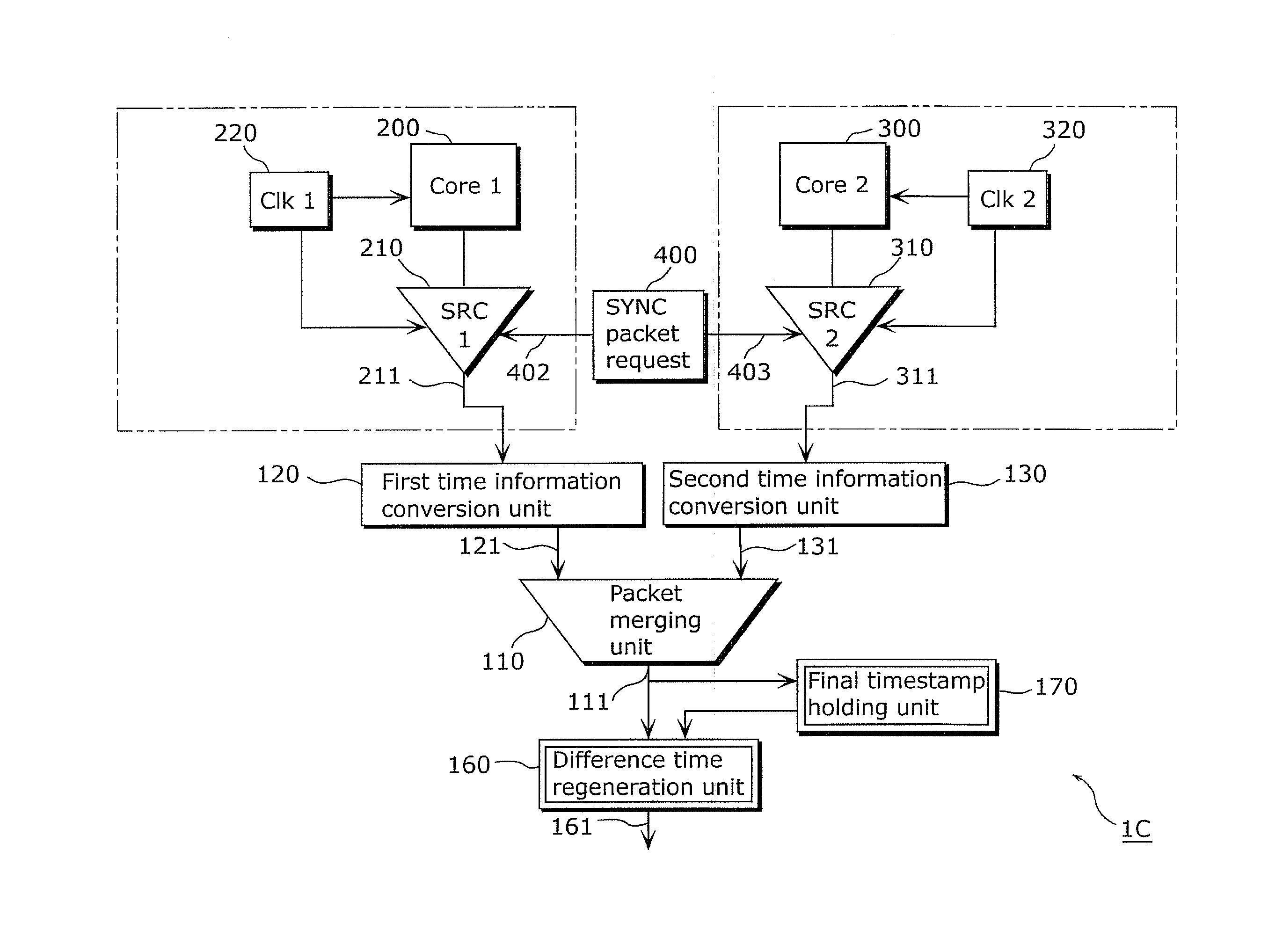
[0038]Here, the first trace data source 210 operates according to the first local clock 220, and outputs trace information items (first trace information items) from a first processor core 200 together with time information items (first time information items) measured according to the first local clock 220. The second trace data source 310 operates according to the second local clock 320, and outputs trace information items (second trace information items) from a second processor core 300 together with time information items (second time information items) measured according to the second local clock 320.

[0039]The first trace packet (trace information item) 211 from the first trace data source 210 is inputted to the packet merging unit 110 ...

embodiment 2

[0062]FIG. 2 is a diagram showing a configuration of an LSI 1A in Embodiment 2.

[0063]FIG. 2 shows the configuration of Embodiment 2, and shows that, in addition to the configuration in FIG. 1, a synchronization packet requesting unit 400 inputs synchronization packet requests (request signal 402, request signal 403) to each of the trace data sources.

[0064]The synchronization packet requesting unit 400 which requests the generation of a synchronization packet (see synchronization packet y1 and so on in FIG. 5) to the respective trace data sources (the first trace data source 210 and the second trace data source 310) is further added to the LSI 1 in Embodiment 1. Then, upon being requested for a synchronization packet by the synchronization packet requesting unit 400, each of the first trace data source 210 and second trace data source 310 inserts a synchronization packet into the trace data (first source stream 211A and so on in FIG. 5) to be outputted by such trace data source.

[0065...

embodiment 3

[0078]FIG. 6 is a diagram showing respective streams in Embodiment 3.

[0079]The examples in Embodiments 1 and 2 describe the case where, in the respective trace data sources, the local timestamps (the first time information item and the second time information item) are provided as elapsed times. In contrast, the local timestamp may be the difference time from a time measured using a local clock (see LTS value of first source stream 211B, and so on, in the top stage in FIG. 6).

[0080]When the time information items of the trace information items of the trace data source are provided as difference times, each of the first time information conversion unit 120 and the second time information conversion unit 130 adds up the present difference time and the respective past different times, and converts the present difference time into an elapsed time. After performing such conversion, each of the first time information conversion unit 120 and the second time information conversion unit 130 ...


PUM


Abstract

Overhead is significant when a timestamp according to a reference time is inserted. In view of this, there is provided an LSI which includes: a first time information conversion unit which converts, into time information of a reference time, time information from a first trace data source; a second time information conversion unit which converts, into time information of a reference time, time information from a second trace data source; and a packet merging unit.

Description

CROSS REFERENCE TO RELATED APPLICATION[0001]This is a continuation application of PCT application No. PCT / JP2009 / 006506 filed on Dec. 1, 2009, designating the United States of America.BACKGROUND OF THE INVENTION[0002](1) Field of the Invention[0003]The present invention relates to a data processing device which, in an information processing apparatus having plural trace data sources, is capable of providing a temporal correlation between the trace data sources.[0004](2) Description of the Related Art[0005]In a large-scale system LSI (Large Scale Integration), a single LSI includes plural processor cores (processing devices), and these perform desired operations while being interrelated. Therefore, in performing system level debugging of such system LSIs, it is necessary to know the temporal context, that is, the temporal correlation arising between plural cores.[0006]Conventionally, a reference timestamp generator is provided, and, at the timing at which the reference timestamp is g...

Claims


Application Information

Patent Timeline
IPC IPC(8): G06F9/30
CPCG06F2201/835G06F11/3466
Inventor UBUKATA, ATSUSHIKAWAMURA, OSAMUOSAKA, MASATAKA
Owner PANASONIC CORP
Learn More