Manufacturing method of glass blank for magnetic recording glass substrate, manufacturing method of magnetic recording glass substrate and manufacturing method of magnetic recording medium

a manufacturing method and technology of glass blank, applied in glass rolling apparatus, glass tempering apparatus, instruments, etc., can solve the problems of cracks on the surface of glass, increase in processing time, and large man-hours for manufacturing a magnetic recording medium substrate, and achieve excellent thickness deviation and flatness, good heat resistance, and small crack defect

Inactive Publication Date: 2011-11-17
HOYA CORP
View PDF3 Cites 23 Cited by
  • Summary
  • Abstract
  • Description
  • Claims
  • Application Information

AI Technical Summary

Benefits of technology

[0013]On the other hand, from the viewpoint of enhancing the productivity of a magnetic recording medium substrate, it is very effective to eliminate a lapping step or to carry out a lapping step in a shorter time, the lapping step being carried out mainly for the purposes of securing the flatness and uniformity in thickness of the magnetic recording medium substrate, adjusting its thickness, and the like. This is because a lapping apparatus is required for carrying out the lapping step, and hence man-hours for manufacturing a magnetic recording medium substrate become larger and the processing time thereof increases. Further, the lapping step may cause the occurrence of cracks in the surfaces of glass. Thus, the present situation is that examination is being made on how to eliminate the lapping step. Here, when the sheet-shaped glass-cutting method and the press method are compared from the viewpoint of eliminating the lapping step, more advantageous is the sheet-shaped glass-cutting method, in which processing is carried out by using a sheet-shaped glass having a higher flatness manufactured by a float method, a down-draw method, or the like. However, the press method has the advantage that glass is used more efficiently compared with the sheet-shaped glass-cutting method.
[0014]In order to eliminate a lapping step or to carry out a lapping step in a shorter time at the time of manufacturing a magnetic recording medium by applying post-processing to a glass blank manufactured by using vertical direct press, it is necessary to make the thickness deviation of the glass blank smaller and to improve the flatness thereof. Here, when a glass blank is produced by vertical direct press, the temperature of a lower mold is set to a temperature sufficiently lower than the temperature of a high-temperature molten glass gob in order to prevent the molten glass gob from melting and bonding to the lower mold. Thus, during the period from placing the molten glass gob in the lower mold until starting press molding, the molten glass gob loses heat through the surface in contact with the lower mold, and hence the viscosity of the lower surface of the molten glass gob placed in the lower mold locally increases. As a result, the press molding is carried out to the molten glass gob having a wide viscosity distribution (temperature distribution), producing portions that resist stretching by press. Besides, a cooling speed after the press molding is different for each site in a glass molded body produced by stretching glass by press molding so as to have a plate shape. Consequently, a glass blank that is manufactured by using vertical direct press is liable to have an increased thickness deviation or to have a deteriorated flatness. Further, in consideration of the above-mentioned mechanism, even in the case of adopting the vertical direct press using a parallel spacer as disclosed in Patent Literature 1, it is difficult to drastically suppress the increase of the thickness deviation of the glass blank and the reduction of the flatness thereof.
[0015]Further, it is described that a polish step can be diminished or eliminated by adopting the horizontal direct press disclosed in Patent Literature 2. Moreover, when this technology is adopted, two projected streaks are concentrically provided in the press-molding surface of each press mold, and hence there are formed, in the surface of a glass blank manufactured, two concentrically-shaped and V-shaped grooves which have a depth equal to one fourth to one third the thickness of the glass blank. Besides, the provision of the V-shaped grooves gives the advantage that a precise processing step applied to the inner diameter side and outer diameter side of the glass blank and a polishing processing step applied to its end surfaces are eliminated. However, when the inventors of the present invention have intensively studies on this technology, the inventors have found that the thickness of the glass blank manufactured tends to be thinner in the inner diameter side rather than the outer diameter side, and hence the thickness deviation cannot be significantly improved compared with the case of using vertical direct press. In addition, the inventors have also found that the glass blank manufactured is liable to have cracks and the yield is liable to lower. Note that the cracks in the glass blank have occurred in V-shaped groove portions, and hence the crack defect is estimated to be attributed to stress concentration in the V-shaped groove portions.
[0019]As the viscosity distribution (temperature distribution) of the molten glass gob becomes wider just before press molding in the vertical direct press, as described above, it is not possible to drastically suppress the increase of the thickness deviation of the glass blank and the reduction of the flatness thereof. Further, even if the horizontal direct press disclosed in Patent Literature 2 was adopted, the thickness deviation of the glass blank was not be able to be improved drastically, and moreover, a crack defect was easily caused. In addition, when a glass blank is manufactured by using a glass material having a higher glass transition temperature for the purpose of improving heat resistance, the shape accuracy of the glass blank inevitably lowers.
[0020]The present invention has been made in view of the above-mentioned circumstances, and an object of the present invention is to provide a method of manufacturing a glass blank for a magnetic recording medium glass substrate, the glass blank being able to be formed into a magnetic recording medium glass substrate having excellent heat resistance by carrying out post-processing, being excellent in thickness deviation and flatness, and having little crack defect, and a method of manufacturing a magnetic recording medium glass substrate and a method of manufacturing a magnetic recording medium each using the method of manufacturing a glass blank for a magnetic recording medium glass substrate.
[0029]According to the present invention, there can be provided the method of manufacturing a glass blank for a magnetic recording medium glass substrate, the glass blank being able to be formed into a magnetic recording medium glass substrate having excellent heat resistance by carrying out post-processing, being excellent in thickness deviation and flatness, and having little crack defect, and the method of manufacturing a magnetic recording medium glass substrate and the method of manufacturing a magnetic recording medium each using the method of manufacturing a glass blank for a magnetic recording medium glass substrate.

Problems solved by technology

This is because a lapping apparatus is required for carrying out the lapping step, and hence man-hours for manufacturing a magnetic recording medium substrate become larger and the processing time thereof increases.
Further, the lapping step may cause the occurrence of cracks in the surfaces of glass.
Consequently, a glass blank that is manufactured by using vertical direct press is liable to have an increased thickness deviation or to have a deteriorated flatness.
Further, in consideration of the above-mentioned mechanism, even in the case of adopting the vertical direct press using a parallel spacer as disclosed in Patent Literature 1, it is difficult to drastically suppress the increase of the thickness deviation of the glass blank and the reduction of the flatness thereof.
However, when the inventors of the present invention have intensively studies on this technology, the inventors have found that the thickness of the glass blank manufactured tends to be thinner in the inner diameter side rather than the outer diameter side, and hence the thickness deviation cannot be significantly improved compared with the case of using vertical direct press.
In addition, the inventors have also found that the glass blank manufactured is liable to have cracks and the yield is liable to lower.
Meanwhile, the magnetic particle having a smaller diameter involves a problem with the deterioration of magnetic characteristics attributed to thermal fluctuation.
On the other hand, when a glass blank for a magnetic recording medium substrate is manufactured by vertical direct press, which has been conventionally used as a method of manufacturing a magnetic recording medium substrate by a press method, there is a problem in that, as a glass material to be used for manufacturing the glass blank has a higher glass transition temperature, the shape accuracy of the glass blank is more liable to lower.
In addition, if the temperature of the molten glass gob is set to a higher one at the time of the press molding, heat becomes liable to be transferred to the rotating table via the lower mold, and as a result, the rotating table supporting the lower mold is eventually deformed by the heat.
Thus, the shape accuracy of the glass blank such as thickness deviation and flatness consequently lowers.
As the viscosity distribution (temperature distribution) of the molten glass gob becomes wider just before press molding in the vertical direct press, as described above, it is not possible to drastically suppress the increase of the thickness deviation of the glass blank and the reduction of the flatness thereof.
Further, even if the horizontal direct press disclosed in Patent Literature 2 was adopted, the thickness deviation of the glass blank was not be able to be improved drastically, and moreover, a crack defect was easily caused.
In addition, when a glass blank is manufactured by using a glass material having a higher glass transition temperature for the purpose of improving heat resistance, the shape accuracy of the glass blank inevitably lowers.

Method used


Image

  • Manufacturing method of glass blank for magnetic recording glass substrate, manufacturing method of magnetic recording glass substrate and manufacturing method of magnetic recording medium
  • Manufacturing method of glass blank for magnetic recording glass substrate, manufacturing method of magnetic recording glass substrate and manufacturing method of magnetic recording medium
  • Manufacturing method of glass blank for magnetic recording glass substrate, manufacturing method of magnetic recording glass substrate and manufacturing method of magnetic recording medium

Examples


examples

[0191]Hereinafter, the present invention is described in more detail based on examples, but the present invention is not limited to the following examples.

[0192]

[0193]Materials such as oxides, carbonates, nitrates, and hydroxides were weighed and mixed enough, yielding each blended material, so that glasses No. 1 to 13 listed in Tables 1 to 5 are obtained. Each blended material was fed into a melting tank in a glass melting furnace, was heated, and was melt. The resultant molten glass was transferred from the melting tank to a fining tank, and bubbles were removed in the fining tank. Further, the molten glass was transferred to an operation tank, was stirred and homogenized in the operation tank, and was caused to flow out from a glass effluent pipe provided in the bottom portion of the operation tank. The melting tank, the fining tank, the operation tank, and the glass effluent pipe were each under temperature control, and in each step, the temperature and viscosity of the glass we...

example b1

[0220]Glass blanks were manufactured by changing the press-molding time to the three levels of 0.2 second, 0.5 second, and 1.0 second in Example A1.

example c1

[0226]The glass blank manufactured in Example A1 was annealed to reduce or remove strain. Next, there was applied scribe processing on a portion that was to serve as the outer periphery of a magnetic recording medium glass substrate and a portion that was to serve as the inner periphery thereof. As a result of the processing, two grooves looking like concentric circles are formed outside and inside. Next, by partially heating the portions on which the scribe processing was applied, cracks are caused to occur along the grooves produced by the scribe processing, by virtue of the difference in thermal expansion of glass, and the outside portion of the concentric circle and the inside portion of the concentric circle are removed. As a result, a disk-shaped glass having a perfect circle shape is yielded.

[0227]Next, shape processing was applied to the disk-shaped glass by using chamfering or the like and its end surfaces were polished. Then, after a first polishing is carried out on the m...


PUM

PropertyMeasurementUnit
glass transition temperatureaaaaaaaaaa
Young's modulusaaaaaaaaaa
viscosityaaaaaaaaaa

Abstract

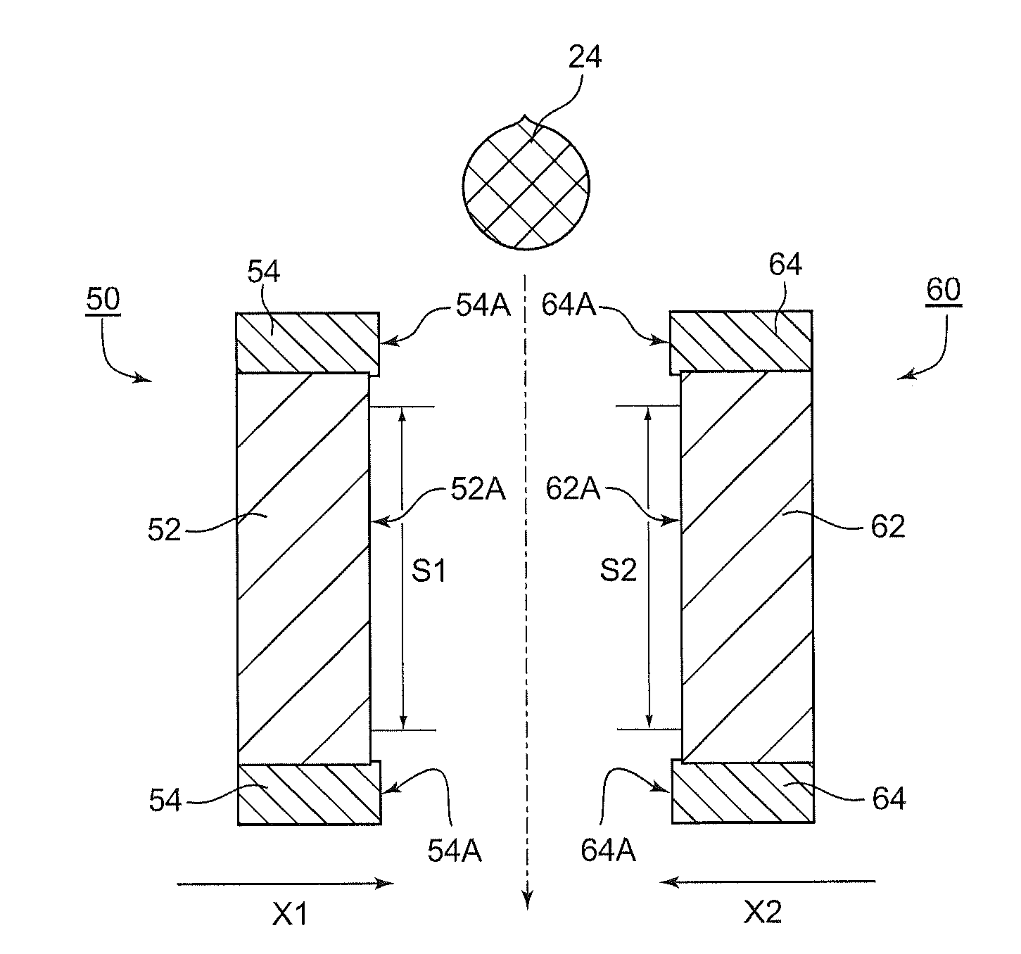
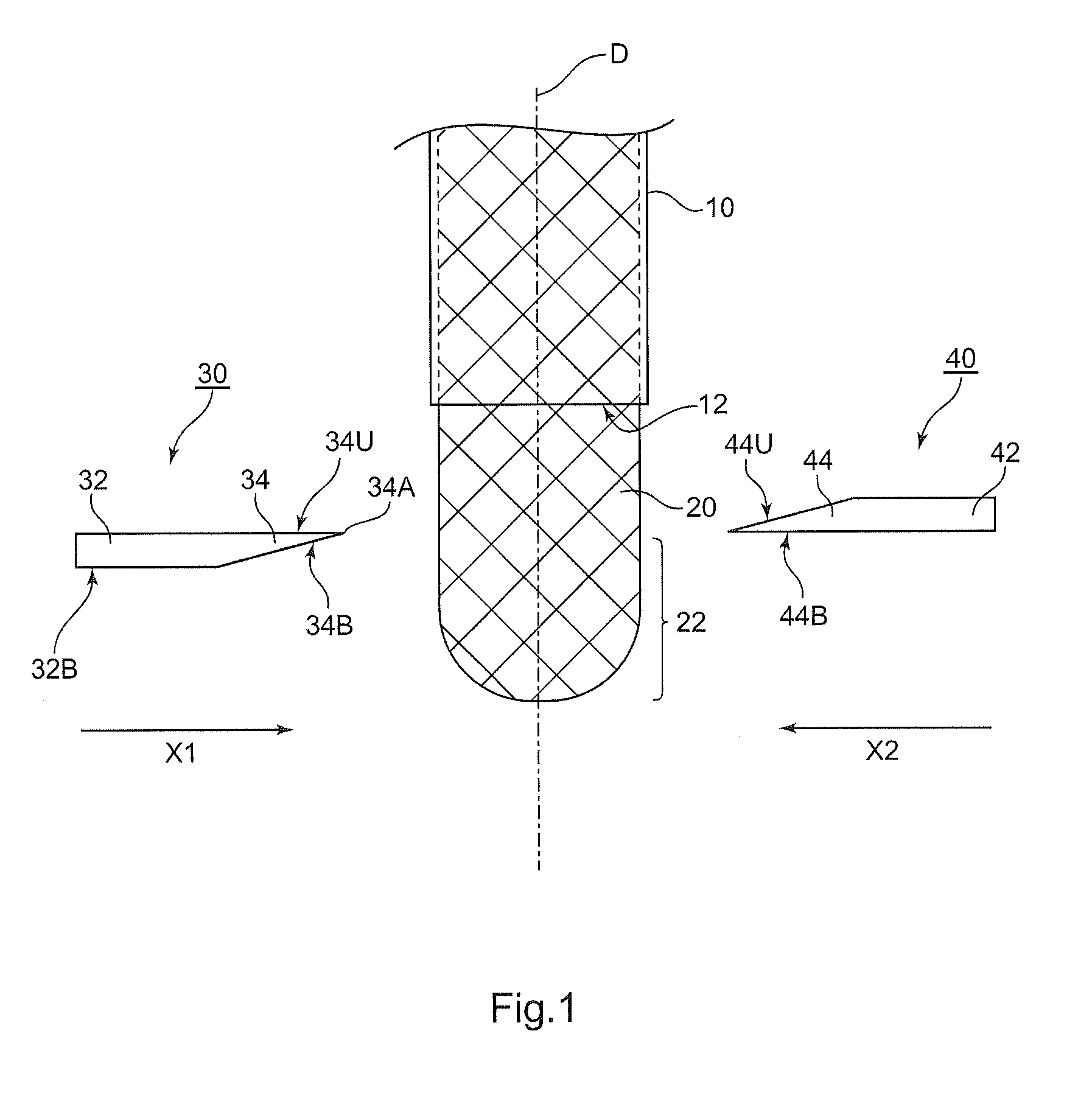
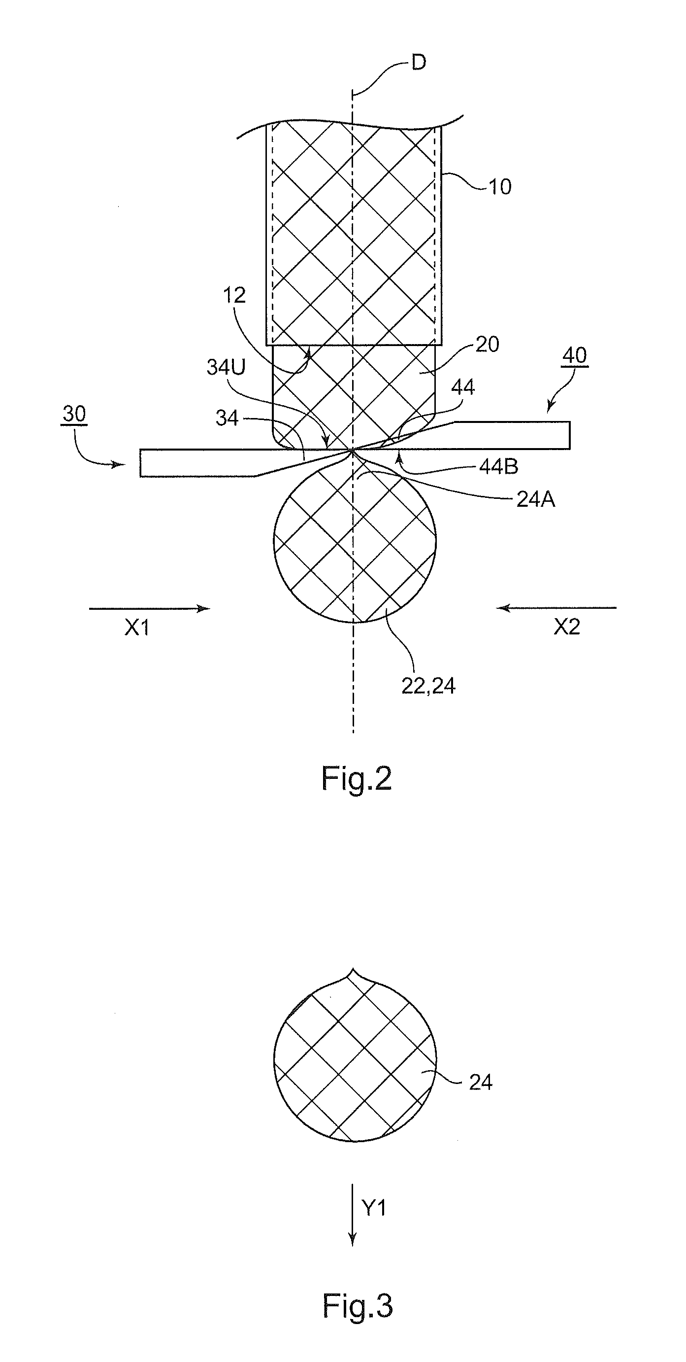
Provided is a method of manufacturing a glass blank for a magnetic recording medium glass substrate, including: manufacturing a glass blank by at least press molding a falling molten glass gob with a pair of press molds both so as to face each other in a direction perpendicular to a direction in which the molten glass gob falls, in which: the molten glass gob is formed of a glass material having a glass transition temperature of 600° C. or more; and when the press molding is carried out so that the molten glass gob is completely extended by pressure and molded into a flat glass between press-molding surfaces of the pair of press molds, at least a region in contact with the flat glass in each of the press-molding surfaces of the pair of press molds forms a substantially flat surface. Also provided are a method of manufacturing a magnetic recording medium glass substrate and a method of manufacturing a magnetic recording medium each using the method of manufacturing a glass blank for a magnetic recording medium glass substrate.

Description

CROSS-REFERENCE TO RELATED APPLICATIONS[0001]The present application claims priority from Japanese Patent Application No. 2010-083778 filed on Mar. 31, 2010 and Japanese Patent Application No. 2010-225966 filed on Oct. 5, 2010, the entirety of which is hereby incorporated by reference.BACKGROUND[0002]1. Technical Field[0003]The present invention relates to a method of manufacturing a glass blank for a magnetic recording medium glass substrate, a method of manufacturing a magnetic recording medium glass substrate, and a method of manufacturing a magnetic recording medium.[0004]2. Background Art[0005]As a method of manufacturing a magnetic recording medium substrate (magnetic disk substrate), there are typically exemplified (1) a method of manufacturing a substrate through a press molding step of subjecting a molten glass gob to press molding with a pair of press molds (hereinafter, sometimes referred to as “press method.” See, for example, Patent Literature 1 and 2) and (2) a method ...

Claims


Application Information

Patent Timeline
Patent Type & Authority Applications(United States)
IPC IPC(8): C03B11/05C03B21/02C03B11/08
CPCC03B7/10C03B11/088C03B2215/11C03B2215/12C03B2215/70G11B5/8404C03C3/093C03C3/095C03C3/097G11B5/7315C03C3/087G11B5/73921Y02P40/57
Inventor OSAWA, MAKOTOMURAKAMI, AKIRASUGIYAMA, NOBUHIROSATOU, TAKASHIMATSUMOTO, NAOMIHACHITANI, YOUICHIOSAKABE, KINOBUISONO, HIDEKITANINO, HIDEKAZUMOTOHASHI, TAKAO
Owner HOYA CORP
Why Eureka
Try Eureka