
Silica container and method for producing the same

a technology of silica and container, applied in the field of silica containers, can solve the problems of shrinkage of molded objects, high cost, high energy consumption, etc., and achieve the effect of suppressing the gaseous bubble generation in the inner wall of the silica container, high durability, and high inhibiting the effect of impurity diffusion

Inactive Publication Date: 2011-11-10
SHIN ETABU QUARTZ PRODS
View PDF8 Cites 45 Cited by
  • Summary
  • Abstract
  • Description
  • Claims
  • Application Information

AI Technical Summary

Benefits of technology

[0052]According to the method for producing a silica container of the present invention, a high inhibiting effect of impurity diffusion, a high durability, and the like during the time that the produced silica container is used at high temperature can be obtained; and in addition, generation of gaseous bubbles in an inner wall of the silica container can be effectively suppressed.
[0053]In addition, the silica container according to the present invention can be given in the silica inner wall a high inhibiting effect of impurity diffusion, a high durability, and the like during its use at high temperature, in spite of a low cost silica container having adequate uniformity of temperature; and in addition, generation of gaseous bubbles in the silica inner wall can be effectively suppressed. As a result, a harmful effect to a material accommodated in the silica container due to gaseous bubbles generated in the silica container inner wall can be suppressed.

Problems solved by technology

However, an expensive compound such as silicon tetrachloride must be used as a raw material for these silica glasses; on top of that, melting temperature and processing temperature of a silica glass is extraordinary high, as high as about 2000° C., thereby leading to a high energy consumption and a high cost.
In these conventional slip casting methods, however, shrinkage of a molded article in a drying process and a sintering process is so significant that a thick silica glass article with a high dimensional precision could not be obtained.
Accordingly, there are problems in each method for producing a silica glass article as mentioned above.
In the methods such as those mentioned above, however, there has been a problem of a high cost because a powdered raw material quartz with high purity is used.
In addition, because various kinds of impure gases are dissolved in a produced silica crucible, the gases are released and then incorporated into a silicon single crystal as gaseous bubbles thereby causing such problems as defects called a void and a pinhole when it is used as a silica crucible for growing of a silicon single crystal; and thus this has been causing problems in production cost as well as quality of the silicon crystal.
In addition, there has been a big problem in durability of the silica crucible because of low etching resistance to a silicon melt at the time of pulling up of a single crystal silicon.
Accordingly, there have been problems frequently that a pulled-up silicon single crystal contains silica fine particles as foreign substances and has defects such as a void and a pinhole.
In addition, there appeared a problem of deformation of a crucible inner surface caused by large expansion of micro gaseous bubbles present inside the crucible during pulling up of a silicon single crystal.
However, with this method, although amount of gaseous bubbles in the silica crucible inner surface could be reduced, an etching resistance to a silicon melt could not be improved by crystallizing the silica crucible inner surface to cristobalite.
In addition, there has been a problem of a poor storage property of a hydrogen-containing powdered raw material because hydrogen molecules doped in the powdered raw material are gradually released to outside during storage of the powdered raw material.
With this method, however, even though amount of gaseous bubbles in the silica glass inner surface layer could be reduced, the OH group concentration in the silica crucible could not be reduced to a certain controlled level, nor was possible to improve durability and heat resistance of the silica crucible by finely crystallizing the inner surface to cristobalite during the time of using the crucible.
In these methods, however, in similar to the foregoing, even though gaseous bubbles inside the silica crucible could be reduced, durability and heat resistance of the crucible could not be improved by protecting the inner surface by finely crystallizing the inner surface to cristobalite during the time of using the silica crucible.

Method used


Image

  • Silica container and method for producing the same
  • Silica container and method for producing the same
  • Silica container and method for producing the same

Examples


example 1

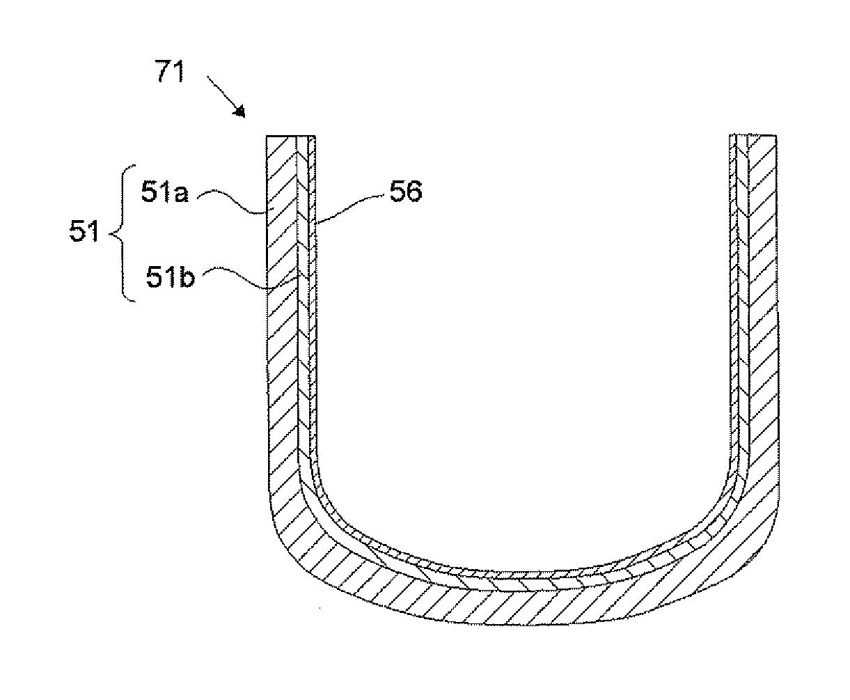
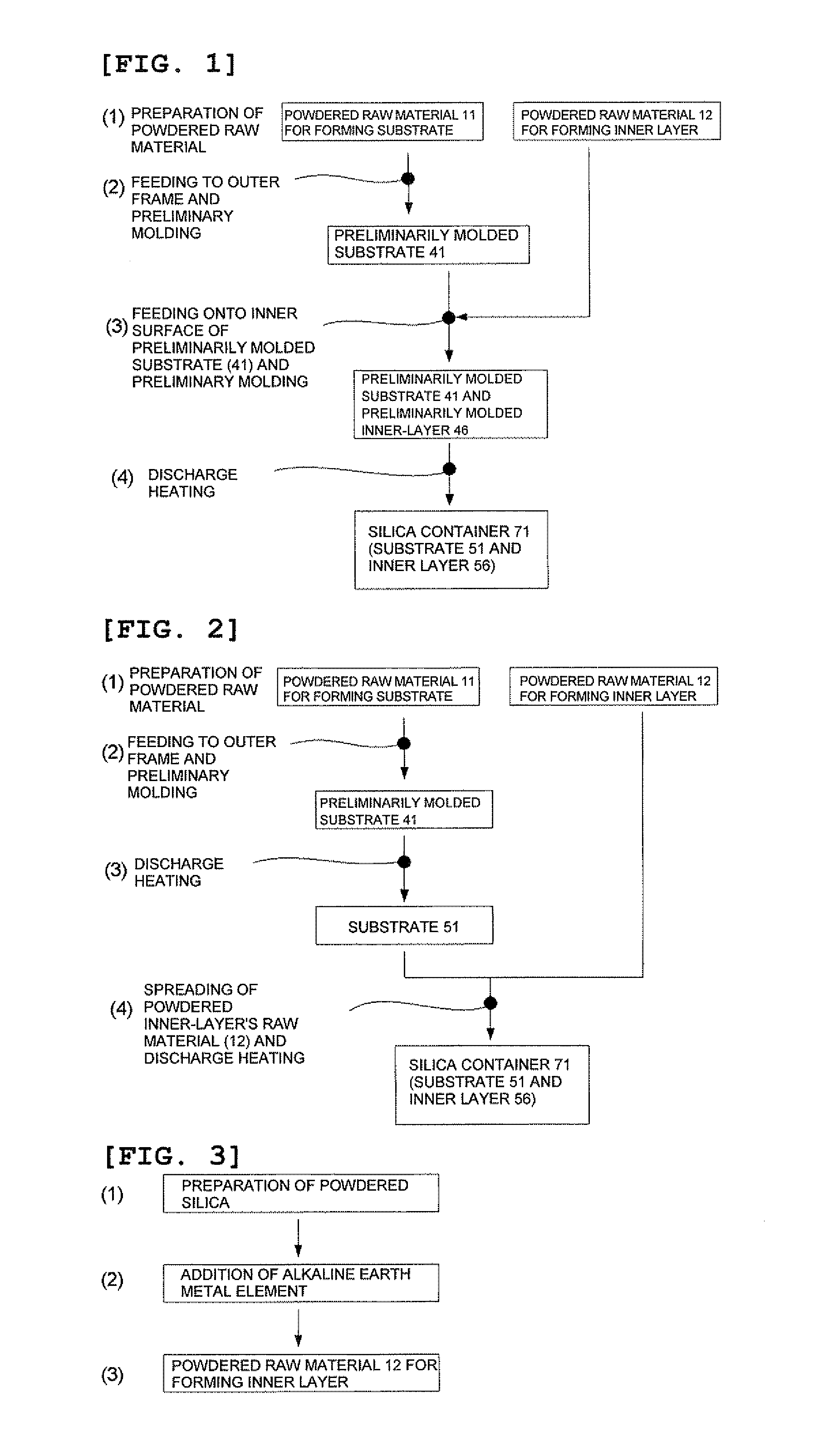
[0174]According to the method for producing a silica container of the present invention shown in FIG. 1 (the first embodiment), the silica container was produced, as described below.

[0175]Firstly, a powdered natural quartz having purity of 99.999% by weight and particle diameter of 50 to 500 was prepared as the powdered raw material 11 for forming the substrate.

[0176]The powdered raw material 12 for forming the inner layer was prepared according to the procedures as shown in FIG. 3. Specifically, at first, a powdered natural quartz having purity of 99.999% by weight and particle diameter of 50 to 500 μm was prepared (FIG. 3 (1)). Then, the powdered natural quartz thus prepared was soaked in an aqueous ethyl alcohol containing barium nitrate with a prescribed concentration, and then dried by heating in a clean oven at 200° C. for 50 hours (FIG. 3 (2)) to obtain the powdered raw material 12 for forming the inner layer (FIG. 3 (3)).

[0177]Then, the powdered raw material 11 for forming t...

example 2

[0179]The silica container 71 was produced in a manner similar to that of Example 1, except that the powdered raw material 12 for forming the inner layer was doped with Ba, the concentration being made approximately twice the amount in Example 1.

example 3

[0180]The silica container 71 was produced in a manner similar to that of Example 1, except that the powdered raw material 12 for forming the inner layer was doped with Ba, the concentration being made approximately four times of the amount in Example 1, and with Al at the same time.


PUM

PropertyMeasurementUnit
particle diameteraaaaaaaaaa
dew-point temperatureaaaaaaaaaa

Abstract

The present invention is a method for producing a silica container having a substrate containing gaseous bubbles in its outer peripheral part and an inner layer comprised of a transparent silica glass formed on an inner surface of the substrate, wherein a powdered raw material for forming a substrate containing Li, Na, and K with the total concentration of 50 or less ppm by weight and a powdered raw material for forming an inner layer containing Ca, Sr, and Ba with the total concentration of 50 to 2000 ppm by weight are prepared; a preliminarily molded substrate is formed in a frame; a preliminarily molded inner layer is formed on an inner surface of the preliminarily molded substrate; and the preliminarily molded substrate and molded inner layer are heated from inside thereof by a discharge-heat melting method under a gas atmosphere containing a hydrogen gas or a helium gas or a gas mixture thereof with the ratio of more than 10% by volume thereby making an outer peripheral part of the preliminarily molded substrate to a sintered body and an inner peripheral part of the preliminarily molded substrate and the preliminarily molded inner layer to a fused glass body. With this, a method for producing a silica container, producible with a low cost and having a high durability and dimensional precision, and a container of this sort can be provided.

Description

TECHNICAL FIELD[0001]The present invention relates to a silica container comprised of mainly silica and to a method for producing it, in particular, to a silica container of a low cost, a high dimensional precision, and a high heat resistance and to a method for producing it.BACKGROUND ART[0002]A silica glass is used for a lens, a prism and a photomask of a photolithography instrument in manufacturing of a large-scale integrated circuit (LSI), for a TFT substrate used for a display, for a tube of a lamp, for a window material, for a reflection plate, for a cleaning container in a semiconductor industry, for a container for melting of a silicon semiconductor, and so forth. However, an expensive compound such as silicon tetrachloride must be used as a raw material for these silica glasses; on top of that, melting temperature and processing temperature of a silica glass is extraordinary high, as high as about 2000° C., thereby leading to a high energy consumption and a high cost. Accor...

Claims


Application Information

Patent Timeline
Patent Type & Authority Applications(United States)
IPC IPC(8): B65D85/00C03B19/06C03B19/09C03B20/00
CPCC03B19/095C30B15/10B65D13/02C30B35/002C30B29/06C03B2201/54C03C3/06C03C2201/54Y02P40/57C03B20/00
Inventor YAMAGATA, SHIGERUUSUI, TOMOMI
Owner SHIN ETABU QUARTZ PRODS
Learn More