
Motor driven rotational sampling apparatus with removable cutting tools for material collection

a sampling apparatus and cutting tool technology, which is applied in the direction of metal working apparatus, manufacturing tools, portable power-driven tools, etc., can solve the problems of not being able to sample at all locations on the surface of all sizes of source materials using this punch, and creating residual artefact products

Inactive Publication Date: 2011-10-27
GE HEALTHCARE BIO SCI CORP
View PDF12 Cites 4 Cited by
  • Summary
  • Abstract
  • Description
  • Claims
  • Application Information

AI Technical Summary

Benefits of technology

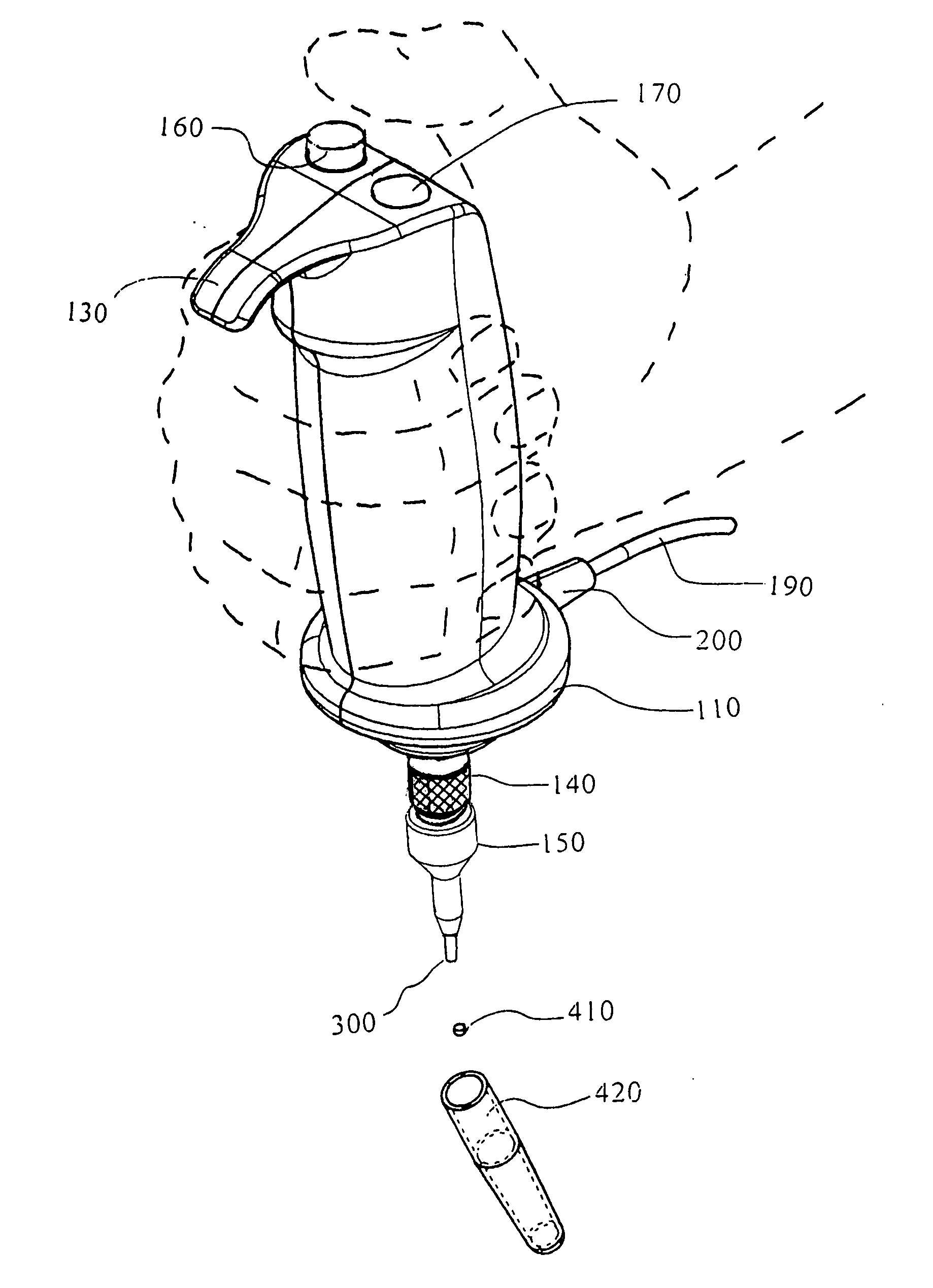
[0037]Samples may be collected from source materials of different sizes, thicknesses and at different geographic locations due to the portability of the new invention. The body of the new invention is a symmetric design allowing it to be held comfortably in either hand like a video game joy stick, with the base of the hand resting on the enlarged flange at the base of the hollow clamshell casing. The grip is grasped in the palm with the front fingers wrapped around the blended contours with the thumb resting on a flat area at the top and to the rear of the hollow clamshell casing. The new invention may be operated with either hand. This ergonomic design avoids using the wrist in a bent (flexed), extended, or twisted position for long periods of time. The unit has been sculpted to complement the contours of the human hand, and the design of the apparatus allows the wrist to maintain a neutral (straight) position. The whole hand is used to grasp the handle and can sit on an enlarged hand rest extending horizontally at the base in a blended design. The thumb also rests on a flat area within easy reach of the activation and ejection buttons located at the top of the clamshell casing. The device is symmetrical, thus equally usable in a one-handed manner by either hand.
[0038]In this invention, the removable threaded cutting tool serves four functions: first the cutting tool cores a sample via the rotation of the drive shaft connected to the motor by way of gears and which the cutting tool is threaded; secondly, the tool retrieves the sample through the coring and downward pressure on the support below the source material which urges the sample into the lumen, thereby allowing the sample to be picked up by the cutting tool; thirdly the lumen acts as an internal storage chamber to hold the sample prior to preferential ejection; fourth the lumen in the cutting tool allows the sample to be transported while held in storage in the lumen. The sample ejection system enables quick, safe and clean removal of the sample from the lumen in the cutting tool. The electric drive eliminates manual exertion in the horizontal plane by eliminating the need for the reciprocating rotary motion of the hand and wrist needed to core a sample from the source material with a manually operated coring punch. Eliminating the wrist action in this new invention allows for the operation of the device with the wrist in the neutral or straight position, eliminating stress to the hand. The hollow casing is held by the entire hand and not the fingers, again reducing another contributing source of wrist and hand stress by dispersing the muscle action to hold the unit over the entire hand and not a few fingers.
[0039]This invention may use a plurality of removable cutting tools of different diameter so that a single cutting tool is threaded to the drive shaft at the distal end of the apparatus below the hand rest. The threaded coupling of the cutting tool to the drive shaft allows for rapid exchange of cutting tools through a threading and un-threading operation. Thereby allowing numerous different diameter cutting tools to be used on a single drive shaft and unit.
[0040]The addition of a motor to rotate the cutting tool, together with the ergonomic design of the clamshell casing, significantly reduces repetitive stress related injury resulting from prior art manual coring and punching devices. The electric motor used to rotate the cutting tool eliminates the reciprocating rotary action of the wrist required to operate the Harris Uni-Core™. The hollow clamshell casing allows the unit to be comfortably gripped in the palm of either hand with the fingers wrapped in front and the thumb on top similar to gripping a video game joystick. This is a recognized grip design people are familiar with, given the widespread use of joysticks, and also similarly designed scientific instruments such as the Eppendorf® pipetters, thereby making this invention less foreign when initially used and easily accepted to the hand. The positioning of the activation trigger is such that it can be easily reached with the thumb of either hand, minimizing strain and adding versatility.
[0041]The motorized rotation of the cutting tool and ergonomic clamshell casing design allows for repeated sampling with minimal strain to the hand. This design also yields an increased sampling range as the invention is capable of sampling a wider variety of source materials of increased thicknesses and dimensions. The tool is designed to accommodate a plurality of cutting tools of different size.

Problems solved by technology

Therefore, areas on source materials of dimensions larger than the maximum horizontal distance the punch / post can reach, will not be possible to sample.
Therefore, it is not possible to sample at all locations on the surface of all sizes of source materials using this punch.
The tearing action of the sampling operation may result in the creation of residual artefact products (e.g. fibres, particles, etc., depending on the composition of the source material) originating from the punched sample and the source material during and following the punching operation.
As there is no means to attach a collection receptacle to the base of the hole below the bottom guide plate, the punched sample may randomly fall through the hole and disperse onto different surfaces or may be co-delivered into a collection receptacle and result in cross sample contamination.
The artefact products may build up around the bottom guide plate and also create potential cross sample contamination through mixing with subsequent sampled materials.
Therefore punch / post punches tear rather then cut samples and may generate cross sample contaminants.
Different punch / post and guide plate hole systems cannot be interchanged on the same main punch body and require purchasing a different punch / post and guide plate hole system for each size of punch required.
Manual paper punches such as those described in the prior art are not designed for sampling materials for subsequent scientific analysis and do not address the problems with artefact product generation which might compromise such analysis.
These punches were designed to be used for hole punching documents or for crafts, but not for use as scientific sampling tools.
Due to the tension of the biasing spring, this operation can create fatigue in the fingers, thumb, hand and wrist muscles after only a few sample punches are produced.
This fatigue and muscle strain will increase over a lengthier period of repetitive punching with this type of punch.
Therefore repetitive stress injury may develop quickly with this type of punch where even the smallest sampling pools to be collected becomes an arduous and painful task.
Each coring tool possesses a sharpened tube of fixed diameter and tubes are not removable.
The Harris Uni-Core™ is a manually operated tool which is not designed for repetitive use, which can lead to repetitive stress injuries, if used for high throughput sampling.
However, the source material thickness and the composition impacts on the manual sampling tool's capability to core a sample from different source materials of differing thickness and composition.
These systems are only designed to sample blood cards and no other source material.
The bench top punch is not portable and cannot be taken to the sample location.
These electric punches also create static electricity build up which may affect sample delivery and lead to potential sample cross contamination.
This may lead to potential sample cross contamination.
The removable cutting tools cut samples from the source material and do not tear samples through the shearing action of a punch / post and guide plate hole arrangement and therefore do not generate the artefact products associated with the bench top electric punching process and which may result in cross sample contamination.
The prior art bench top electric punching units do not offer direct line of sight for confirming sample delivery following punching as the combination sample stage / guide plate hole is larger than the guide plates on paper punches, thereby blocking the operator's view of sample delivery into the collection receptacle below the guide plate hole.
This is not possible with punch / post punching systems.
A search did not disclose any prior art electric motorized rotational sampling tools with removable threaded cutting tools with a plurality of coring diameters which could be used on the same main unit and with the same ejection rod diameter.

Method used


Image

  • Motor driven rotational sampling apparatus with removable cutting tools for material collection
  • Motor driven rotational sampling apparatus with removable cutting tools for material collection
  • Motor driven rotational sampling apparatus with removable cutting tools for material collection

Examples


Embodiment Construction

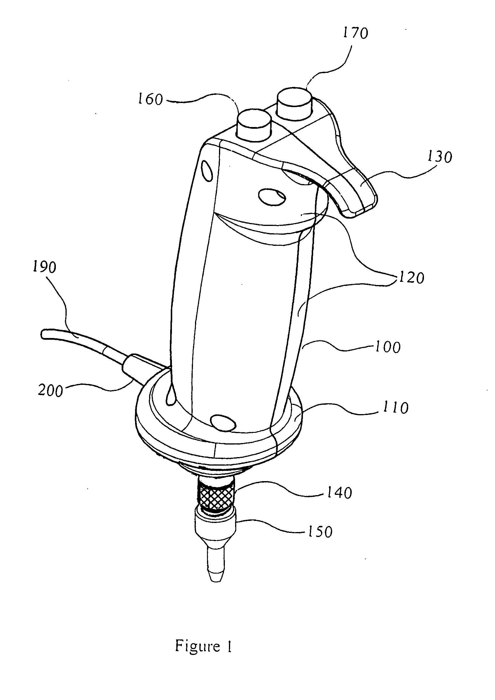
[0060]Referring to FIG. 1, a preferred embodiment of a sample collection device constructed in accordance with the principles of the invention is shown. A handle feature 100 blends to a horizontal flange feature 110 at the bottom as a hollow clamshell casing. A drive shaft 140 with its lower end below the flange 110 holds the threaded removable cutting tool 150. To facilitate ease of holding the unit, finger contours 120 are included on the front of the casing. To eliminate slipping of the hollow clamshell handle 100 through the hand a horizontal extension 130 has also been added as a blended feature above the finger contours 120. The motor actuation button 160 and the ejection button 170 are positioned at the top of the hollow clamshell casing 100. The power supply cord 190 extends from a cord strain release 200 which extends from the rim of the flange 110.

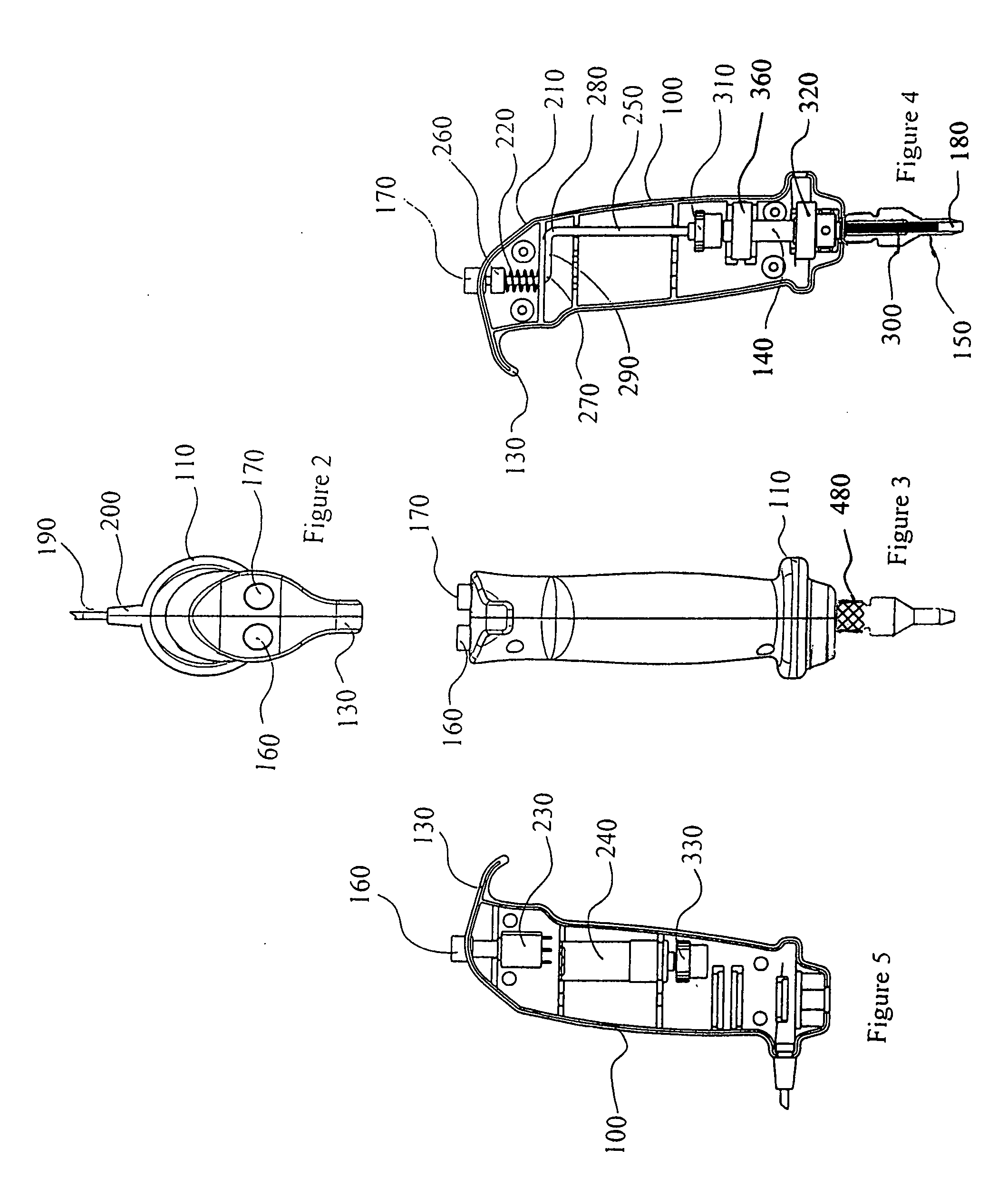
[0061]FIGS. 2 and 3 repeat the preferred embodiments described in FIG. 1 but are an overhead view and a projected front view of...


PUM


Abstract

A motorized apparatus to simultaneously excise, retrieve, temporarily store and transport a sample of material has a hollow clamshell casing with a blended contoured grip for the fingers, a horizontal extension to eliminate slippage when held in a user's hand, and a flange bottom portion from which a removable cutting tool threaded to a drive shaft extends downwards. Within the clamshell casing an electric motor is mounted which drives, via gears, a drive shaft which rotates a cutting tool threaded to the distal end of the drive shaft. The end of the cutting tool, distal from the clamshell casing, forms a cutting edge circumscribing a circular region. An ejection rod slides reciprocally within the cutting tool between a stowed position and an expulsion position. Users core a sample from the source material by engaging contact between the cutting edge of the cutting tool and the surface of the source material, applying pressure against the surface of the source material while simultaneously activating the motor to rotate the cutting tool. The cutting region of the cutting tool passes through the source material contacting the support surface below the source material which urges the cored sample into the lumen of the cutting tool. The sample may be stored in the lumen or transported. Activation of the ejection rod moves from the stowed position towards the expulsion position displacing the temporarily stored sample from the lumen space in the cutting tool into the appropriate collection receptacle or onto a desired surface.

Description

BACKGROUND OF THE INVENTION[0001]1. Field of Invention[0002]Micro-sampling devices are used to retrieve a sample of material from a larger source material by some means such as slicing, cutting, scooping, punching, boring or coring. Examples would include punching a disc of paper from a sheet of paper, coring a piece of cloth from a larger piece of clothing, scooping gel from a petri dish, slicing a piece of tissue from a larger piece of tissue, etc. The retrieved samples may then be subsequently managed and further analyzed.[0003]The widely available single-hole, manually operated office paper punch has been suitably adopted to sample different materials such as paper, leaves, etc., for scientific analysis. The paper punch consists of a punch / post sliding vertically through a biasing spring positioned between holes in two guide plates. The biasing spring keeps the punch / post in the stowed position above a bottom guide plate with a hole where the punch / post passes through to punch a...

Claims


Application Information

Patent Timeline
IPC IPC(8): B26D7/18B26D3/10
CPCB26D7/18G01N1/08B26F1/16
Inventor HARRIS, JOEL STEVEN
Owner GE HEALTHCARE BIO SCI CORP
Learn More