Eureka AIR delivers breakthrough ideas for toughest innovation challenges, trusted by R&D personnel around the world.

Chemical sensors containing carbon nanotubes, method for making same, and uses therof

Inactive Publication Date: 2011-10-06
COMMISSARIAT A LENERGIE ATOMIQUE ET AUX ENERGIES ALTERNATIVES
View PDF1 Cites 17 Cited by
  • Summary
  • Abstract
  • Description
  • Claims
  • Application Information

AI Technical Summary

Benefits of technology

[0033]The present invention aims at providing a device of the chemical sensor type which meets the needs and technical problems mentioned earlier, i.e. a device sensitive to chemical agents notably to optionally toxic, gaseous chemical agents. The device of the present invention is in particular distinguished by the fact that it is selective and highly sensitive, even at room temperature. It is therefore not absolutely necessary to add a heating system to it, which is costly in terms of energy. Moreover, the device of the present invention is simple to form.
[0089]Any technique known to one skilled in the art allowing two electrodes to be prepared at the surface of a support may be used within the scope of the present invention. However, the use of long carbon nanotubes with several graphene layers advantageously having a length greater than or equal to 20 μm, gives the possibility of contemplating large interelectrode spacings. Advantageously, these spacings are comprised between 1 and 300 μm; notably comprised between 5 and 200 μm; in particular, greater than 20 μm and, more particularly, greater than 50 μm. With this, it is possible to have access to simple and relatively inexpensive simple techniques for elaborating electrodes, such as metal deposition techniques in vacuo for example by thermo-evaporation by plasma (or PECVD <<Plasma-Enhanced Chemical Vapor Deposition>>) or by sputtering.
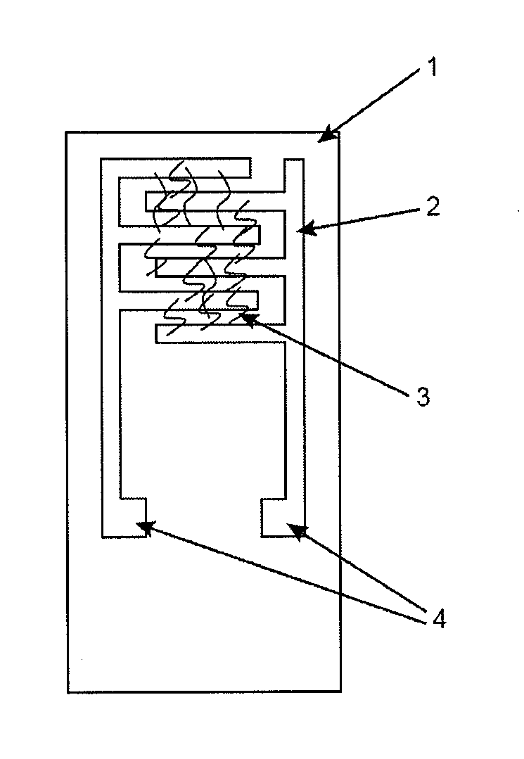
[0091]The carbon nanotubes which the device of the present invention comprises, have an orientation which is substantially perpendicular with respect to the two electrodes. Further, these nanotubes are arranged homogeneously on said electrodes. By <<homogeneous arrangement>> is meant that the carbon nanotubes are regularly distributed between the electrodes with few or no clusters of nanotubes. FIG. 8B is an illustration of a homogeneous arrangement of nanotubes. Thus, the use of a technique such as the dielectrophoresis technique for positioning the nanotubes on the electrodes leads to a homogeneous arrangement of the carbon nanotubes, preferentially oriented perpendicularly between the advantageously interdigitated electrodes. With this technique, it is also possible to only use a small amount of carbon nanotubes for ensuring the contact between the electrodes, which reduces the manufacturing costs of the device and increases the specific surface area in contact with ambient air.
[0097]The device, object of the present invention allows selective and low content detection (<1 ppm) of notably toxic, gaseous chemical agents, such as in particular chlorine. This detection is possible at a moderate temperature, advantageously below 100° C., notably below 80° C., in particular below 60° C., and more particularly, below 40° C. More preferably, the detection is carried out at room temperature, i.e. at a temperature comprised between 20° C.±5° C. Under such conditions, the chlorine, as an example, may be detected for contents below 27 ppb. By being able to carry out detection at room temperature, it is possible to avoid the addition of a heating system to the device for its proper operation.
[0122]The thermal environment depends on temperature. It is easy to control it with heating means customarily used by one skilled in the art. The use of a thermostated environment has a particular advantage since it allows accurate control of the reaction conditions.

Problems solved by technology

However, strong constraints restrict the manufacturing of such chemical sensors, the latter having to be both sensitive and selective.
To these fundamental constraints, other more secondary issues may be added to the specifications sheet.
The main drawback of this type of sensor is therefore their low sensitivity.
The drawback of this method however is the non-portability of the measurement method, preventing a measurement in situ.
The drawback of this type of sensor is the manufacturing cost of a complete device which notably comprises the sensitive film, a diode and a detector.
However, let us note that the detection only becomes effective when these sensors are heated, typically at temperatures above 150° C. The fact that they do not operate at room temperature is their main flaw.
Secondly, carbon nanotubes have a very high electric conductivity which proves to be extremely sensitive to the adsorption of molecules on their surface, and therefore more generally to their environment.
The design of a device meeting the whole of the constraints listed earlier still remains presently a challenge which is only partly faced.
The manufacturing of such a sensor therefore is a very important issue.

Method used


Image

  • Chemical sensors containing carbon nanotubes, method for making same, and uses therof
  • Chemical sensors containing carbon nanotubes, method for making same, and uses therof
  • Chemical sensors containing carbon nanotubes, method for making same, and uses therof

Examples


example 1

Preparation of Suspensions of Long Multi-Sheet Carbon Nanotubes

[0171]The suspensions of different concentrations (1˜100 mg / L) of long multi-sheet carbon nanotubes (400 μm) in isopropanol are prepared with an ultrasonic probe. In this example, the suspensions are subject to ultrasounds for 8 minutes with a power of 250 W. Up to 10 mg / L, the suspensions are (visibly) stable for several hours.

[0172]For more concentrated suspensions, flocculation or sedimentation of the nanotubes appears after a few tens of minutes. The suspensions having a nanotube concentration of 5 to 10 mg / L are used for making sensors based on the use of non-functionalized nanotubes.

[0173]The suspensions of functionalized nanotubes, as for them, are stable in isopropanol for a few hours or even a few days at concentrations of less than 100 mg / L. The suspensions having a nanotube concentration in the range from 20 to 100 mg / L are used for preparing sensors based on functionalized nanotubes.

example 2

Effect of Dielectrophoresis During the Preparation of Sensors According to the Invention

[0174]The applied dielectrophoresis conditions are a 5 MHz sinusoidal 20 V peak-to-peak voltage.

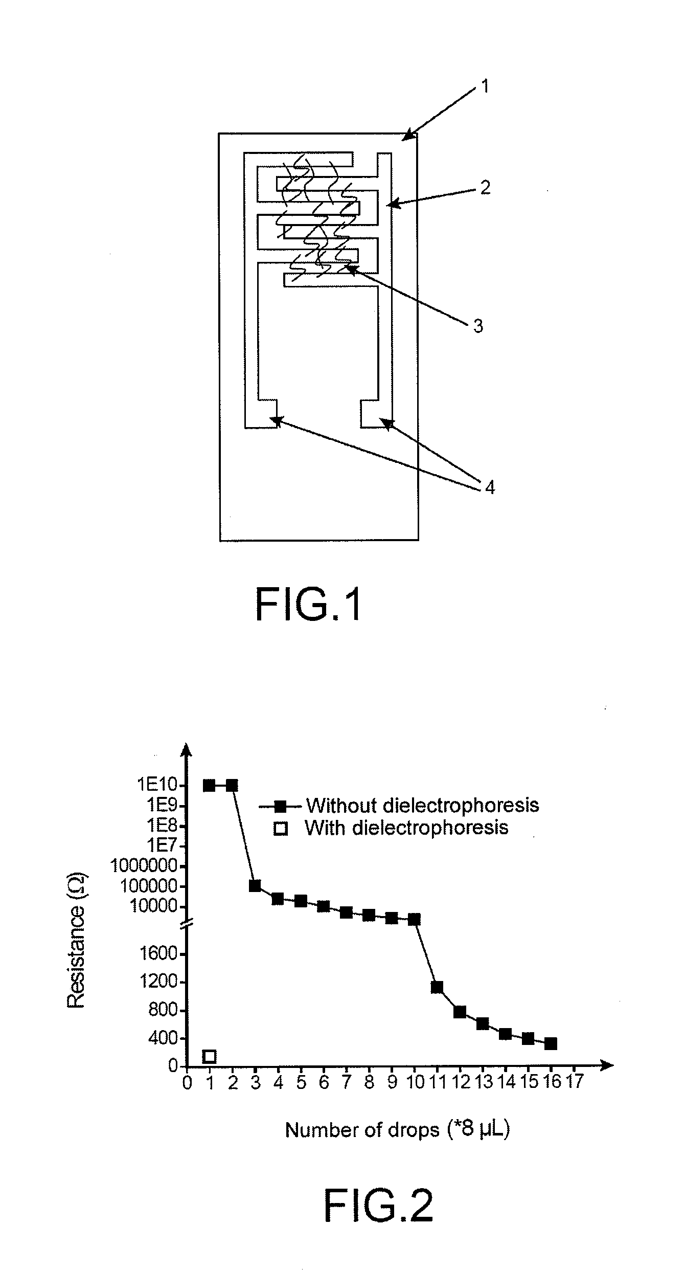
[0175]The initial resistance of a sensor depending on the number of drops (8 μL per drop) deposited on the electrodes with and without dielectrophoresis was investigated (FIG. 2). The nanotube concentration for the suspension used for both sensors is 5 mg / L.

[0176]In this example, with dielectrophoresis, it is possible to reduce by a factor of 16 the number of deposited drops in order to attain the proper initial resistance value.

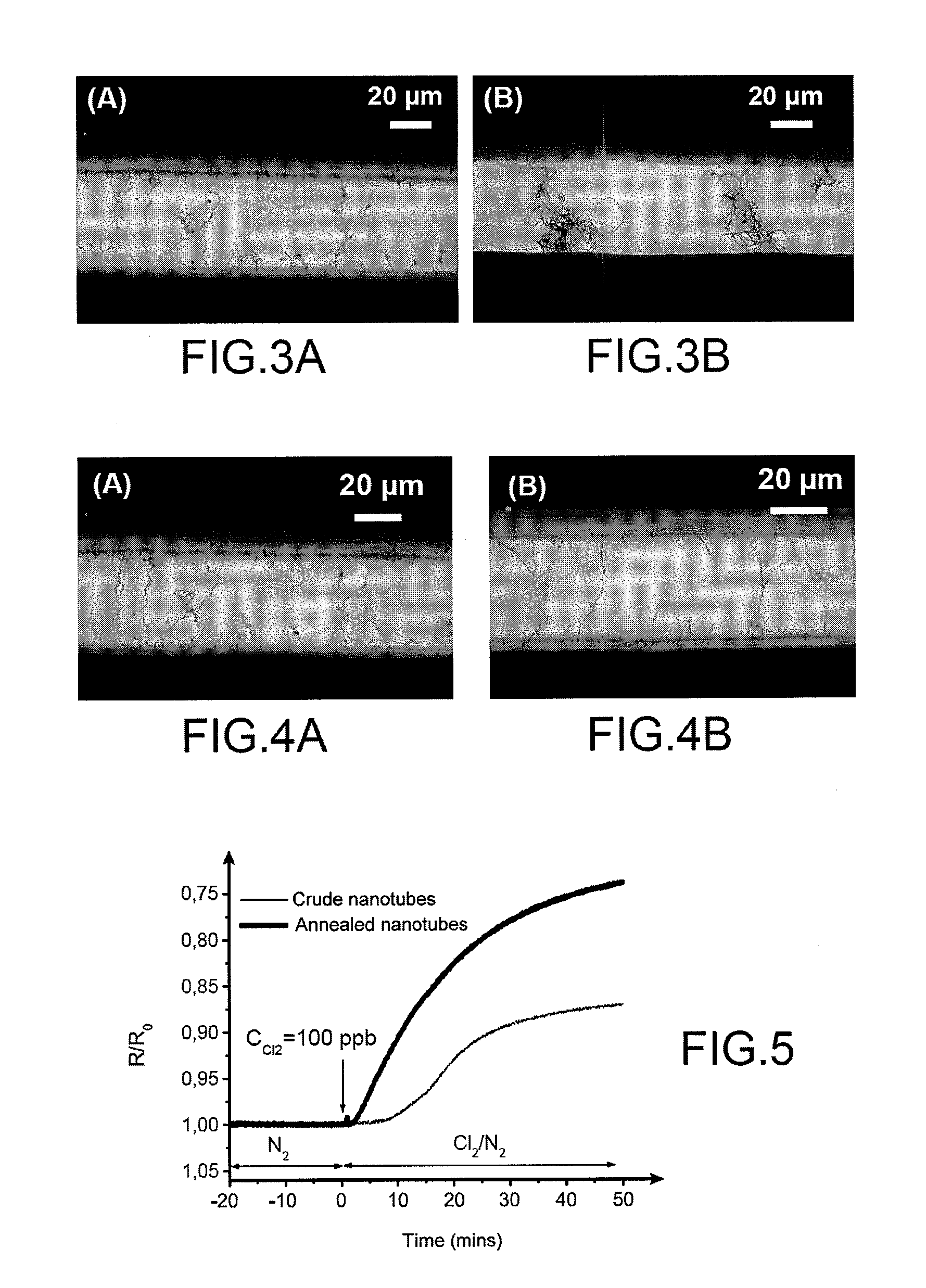
[0177]Further, the optical microscopy image of multi-walled carbon nanotubes deposited on the interdigitated electrodes by dielectrophoresis, after depositing a suspension drop, reveals that the nanotubes are quasi individual and have a preferential orientation perpendicular to the electrodes (FIG. 3A). The nanotubes are, on the contrary, organized as a cluster as viewed on the...

example 3

Effect of Annealing on Carbon Nanotubes

[0178]This example aims at comparing a device based on > carbon nanotubes and a device based on carbon nanotubes annealed at 2,000° C. for one hour under argon.

[0179]FIGS. 4A and 4B are optical microscopy images obtained for respectively > or > multi-walled carbon nanotubes, deposited on the interdigitated electrodes by dielectrophoresis after depositing one drop of suspension (5 mg / L).

[0180]The sensitivity of such sensors based on > and > nanotubes towards chlorine diluted in nitrogen at a content of 100 ppb was also compared. The results shown in FIG. 5 show that the sensitivity (S═(R—R0) / R0)*100) at 50 mins of the sensor based on > nanotubes is twice greater, as compared with that of the sensor based on > nanotubes (26 versus 12.5).

[0181]Further, the sensitivity (S═(R—R0) / R0)*100) towards chlorine diluted in nitrogen at a content of 27 ppb of a sensor based on > nanotubes and measured at 50 minutes is 7% (FIG. 6).


PUM

PropertyMeasurementUnit
Lengthaaaaaaaaaa
Lengthaaaaaaaaaa
Electric propertiesaaaaaaaaaa

Abstract

A device is disclosed for detecting at least one chemical compound comprising at least one carbon nanotube with several graphene layers, on which is grafted at least one molecule bearing group G1 capable of reacting with the chemical compound or a precursor of such a group G1. The uses and the method of making such a device is also disclosed.

Description

TECHNICAL FIELD[0001]The present invention relates to the field of detection, identification and quantification of gaseous chemical species and notably toxic gaseous chemical species.[0002]The present invention more particularly relates to a device of the chemical sensor type comprising functionalized multisheet carbon nanotubes and allowing such a detection, identification and quantification, to its preparation method and to its uses. The functionalization appears as a fine layer of polymer or else as a few chemical groups at the surface of the carbon nanotubes.PRIOR ART[0003]Detection of toxic chemical substances in the atmosphere is an important guarantee of our safety both in civilian or professional life. Limiting average exposure values are moreover already established for a great number of chemical agents. In this background, development of performing chemical sensors, i.e. which transform chemical information into a useful analytic signal, is therefore an absolute necessity....

Claims


Application Information

Patent Timeline
IPC IPC(8): G01N33/00G01N27/04C25D13/00C25D13/20B82Y15/00B82Y40/00
CPCB82Y15/00B82Y30/00Y10T436/204998Y10T436/16Y10T436/19Y10T436/18Y10T436/22Y10T436/205831Y10T436/172307Y10T436/163333Y10T436/175383Y10T436/214Y10T436/142222
Inventor MAYNE-L'HERMITE, MARTINEPALACIN, SERGECHENEVIER, PASCALECHANCOLON, JEROMEGOHIER, AURELIEN
Owner COMMISSARIAT A LENERGIE ATOMIQUE ET AUX ENERGIES ALTERNATIVES
Why Eureka
Eureka Blog
Learn More