
Plasma processing apparatus, plasma processing method and end point detection method

a processing apparatus and plasma technology, applied in the field of plasma processing, can solve the problems of difficult application of this method to end point detection in other than etching, plasma oxidation or plasma nitridation processing, and the difficulty of precisely determining the end point, so as to achieve more direct and precise end point detection, ensure the uniformity of processing between wafers and lots, and improve the effect of precision

Inactive Publication Date: 2011-07-21
TOKYO ELECTRON LTD
View PDF4 Cites 12 Cited by
  • Summary
  • Abstract
  • Description
  • Claims
  • Application Information

AI Technical Summary

Benefits of technology

The present invention provides a method for detecting the end point of plasma processing with high precision. This is achieved by measuring the integrated value of the particle number of an active species that is generated in the plasma and moving towards the processing object. The method uses a plasma processing apparatus that includes a processing chamber, a plasma generation means, a measurement means for measuring the integrated value of the particle number, and a control means for controlling the operation of the plasma processing apparatus. The method allows for the secure and uniform completion of plasma processing without being influenced by the plasma generation conditions or the state of plasma. The method can be used in various plasma processings, such as plasma oxidation, plasma nitridation, plasma etching, and plasma cleaning.

Problems solved by technology

A problem in plasma processing is difficulty in determining its end point precisely.
However, because the measuring object is the thickness of a film, it is difficult to apply this method to end point detection in processing other than etching, such as plasma oxidation or plasma nitridation.
It is therefore difficult to apply this technique to plasma oxidation or plasma nitridation.

Method used


Image

  • Plasma processing apparatus, plasma processing method and end point detection method
  • Plasma processing apparatus, plasma processing method and end point detection method
  • Plasma processing apparatus, plasma processing method and end point detection method

Examples


Embodiment Construction

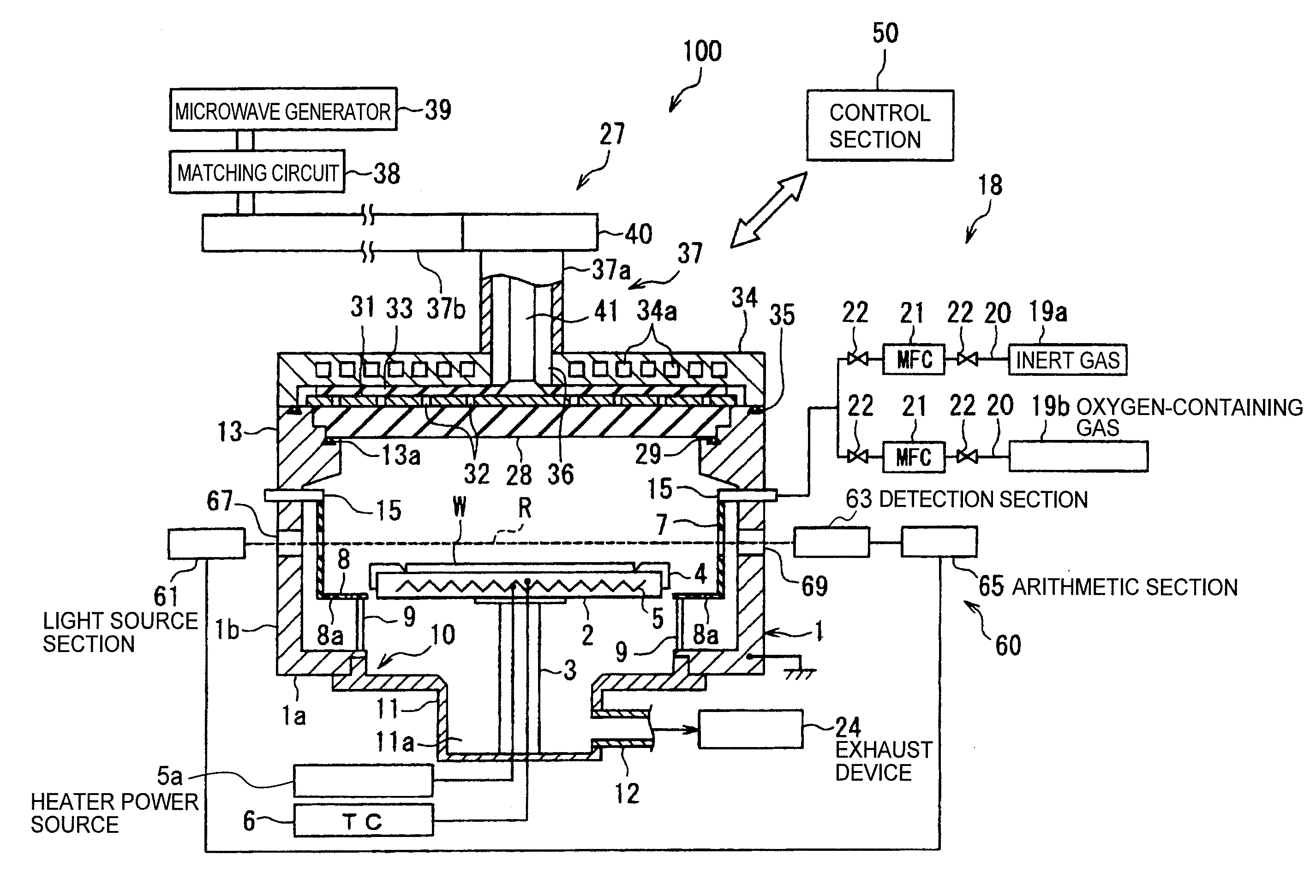
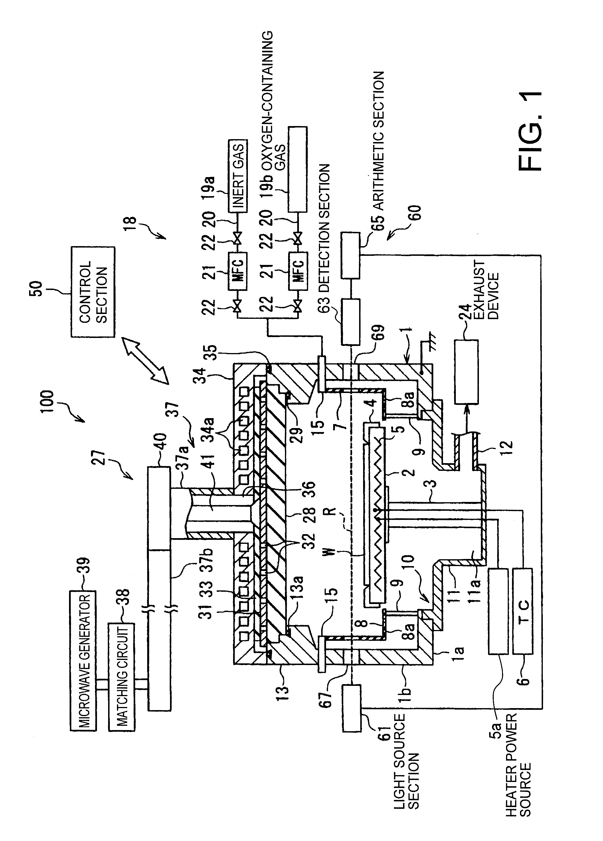
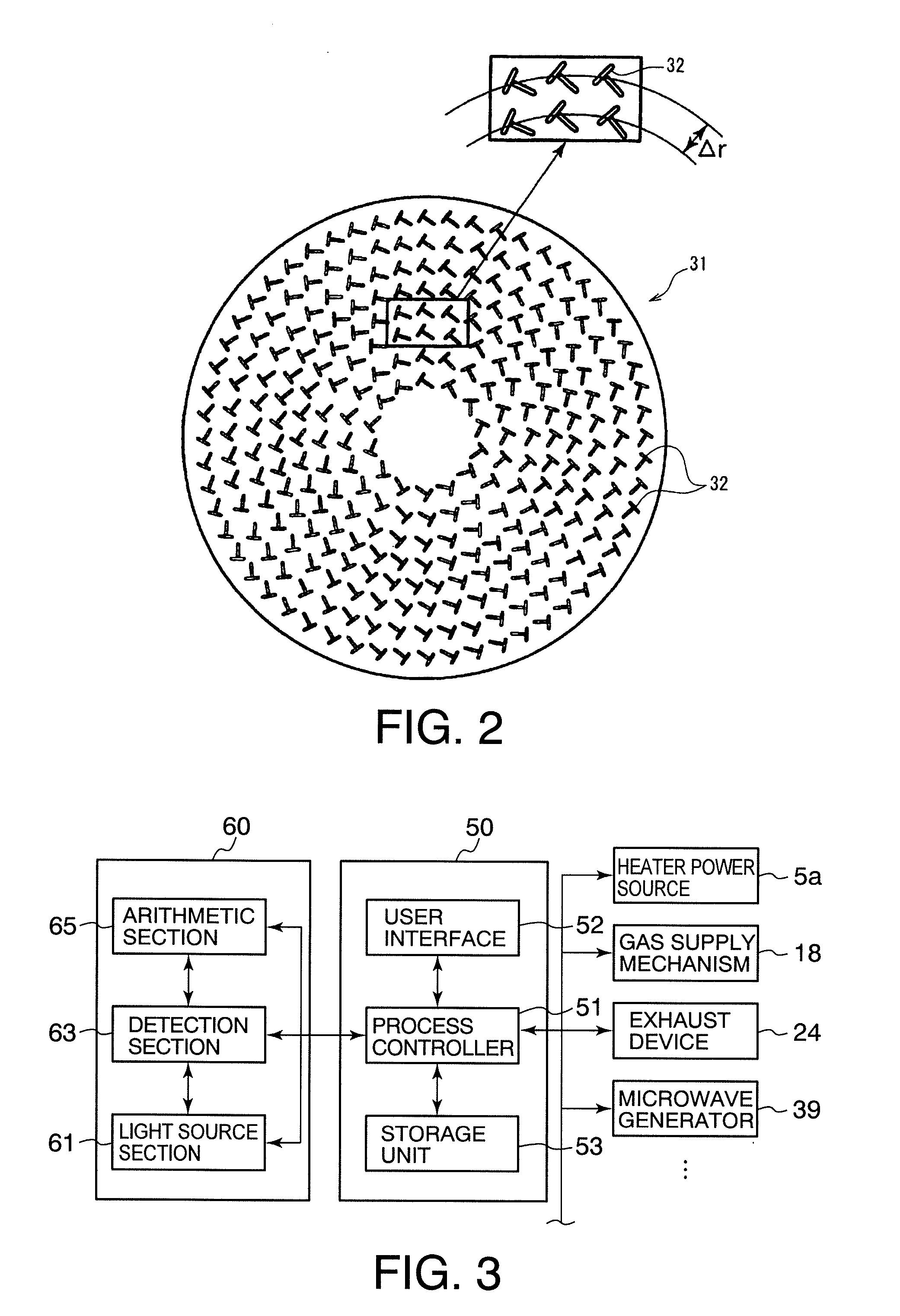
Preferred embodiments of the present invention will now be described in detail with reference to the drawings. The following description illustrates, by way of example, oxidation processing of a processing object by means of a plasma. FIG. 1 is a cross-sectional diagram schematically showing the construction of a plasma processing apparatus 100 according to a first embodiment of the present invention. FIG. 2 is a plan view of the plane antenna of the plasma processing apparatus 100 of FIG. 1. FIG. 3 is a diagram illustrating the schematic construction of the control system of the plasma processing apparatus of FIG. 1.

The plasma processing apparatus 100 is constructed as an RLSA microwave plasma processing apparatus capable of generating a high-density, low-electron temperature, microwave-excited plasma by introducing microwaves into a processing chamber by means of an RLSA (radial line slot antenna), which is a plane antenna having a plurality of slots which are through holes. The p...


PUM

PropertyMeasurementUnit
temperatureaaaaaaaaaa
frequenciesaaaaaaaaaa

Abstract

A plasma processing apparatus (100) includes: a plasma generation means for generating a plasma in a processing chamber (1); a measurement section (60) for measuring an integrated value of the particle number of an active species contained in the plasma and moving toward a processing object (wafer W); and a control section (50) for controlling the apparatus in such a manner as to terminate plasma processing when the measured integrated value has reached a set value. The measurement section (60) measures the particle number of the active species by emitting a predetermined laser light from a light source section (61) toward the plasma, and receiving the laser light in a detection section (63) provided with a VUV monochromator.

Description

TECHNICAL FIELDThe present invention relates to a plasma processing apparatus and a plasma processing method for processing a processing object by using a plasma, and to a method for detecting the end point of plasma processing.BACKGROUND ARTPlasma processing is known which performs oxidation, nitridation, etc. of a processing object, such as a semiconductor wafer, by using a plasma. Plasma processing is capable of processing at a low temperature, such as about 400° C., and therefore has an advantage over thermal oxidation processing or the like in that thermal budget can be reduced, thereby suppressing thermal strain, etc. of a semiconductor wafer.A problem in plasma processing is difficulty in determining its end point precisely. It is a conventional practice in plasma processing to set a processing time based on the rate of processing (e.g. oxidation rate, nitridation rate or etching rate) in advance, and terminate the plasma processing by time control. However, with reference to...

Claims


Application Information

Patent Timeline
Patent Type & Authority Applications(United States)
IPC IPC(8): C23F1/08C23F1/00C23C16/455C23C16/511C23C16/52
CPCH01J37/32963H01L21/02252H01L21/02238H01L21/3065H01L21/31
Inventor KABE, YOSHIROOTA, KINYAKITAGAWA, JUNICHI
Owner TOKYO ELECTRON LTD
Learn More