
Amtec with heat pipe

Active Publication Date: 2011-07-14
KOREA INST OF ENERGY RES
View PDF11 Cites 10 Cited by
  • Summary
  • Abstract
  • Description
  • Claims
  • Application Information

AI Technical Summary

Benefits of technology

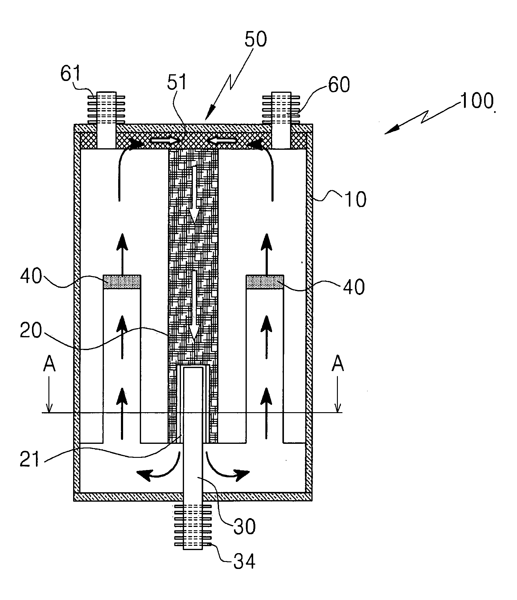
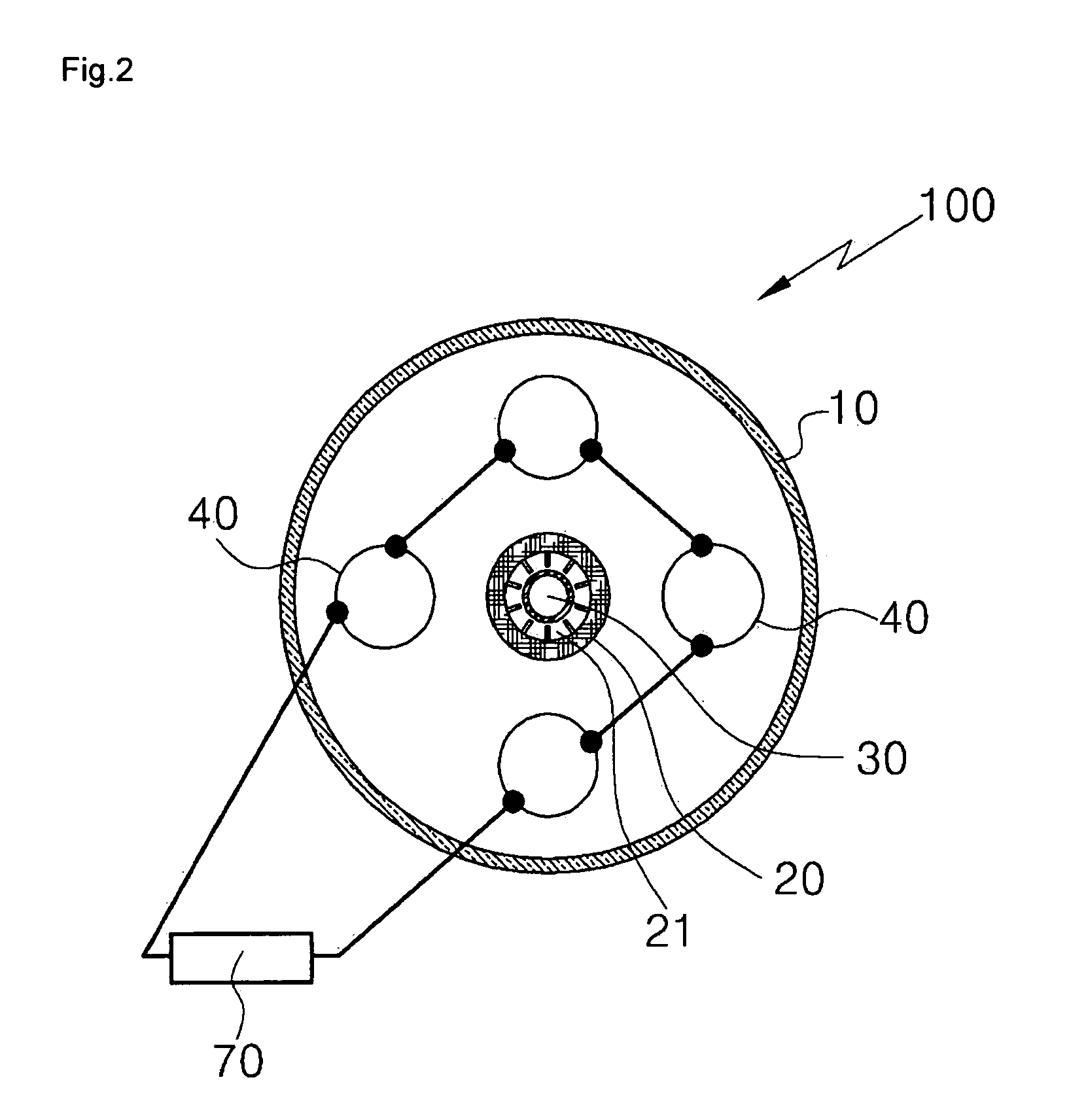
[0013]The present invention provides an AMTEC which is installed with a heat pipe as an heater and / or a condenser, in which a vaporizing of a metal fluid is accomplished even though a difference between a temperature of heat source and a temperature needed for vaporizing the metal fluid is small, and a condensing of the metal fluid vapor is possible even though a difference between a temperature of the metal fluid vapor and a temperature needed for condensing the metal fluid vapor is small so that the AMTEC becomes small in size and the efficiency of thermal to electric conversion is improved through using the heat pipe for vaporization of the metal fluid and for condensing of the metal fluid vapor.
[0014]The present invention also provides an AMTEC which is installed with a heat pipe as a heater in which heat is directly transferred to a vaporizer of the AMTEC by using a latent heat of an operating fluid of the heat pipe, so that a metal fluid is vaporized at a heat source of a low temperature and therefore the thermal efficiency is improved through installing the heat pipe as a heater.

Problems solved by technology

A semiconductor thermoelectric generation system has been used as a power source for space application but there are drawbacks of low efficiency and heavy weight in generation system.
Further, since the conventional condenser releases heat by conduction, there is a problem in that the AMTEC is large in size.
Further, since the condenser for condensing the metal fluid vapor operates by conduction, there is a problem in that the heat conduction area increases.

Method used


Image

  • Amtec with heat pipe
  • Amtec with heat pipe
  • Amtec with heat pipe

Examples


Embodiment Construction

[0025]The present invention will now be described more fully hereinafter with reference to the accompanying drawings, in which preferred embodiments of the invention are shown.

[0026]It will be understood that words or terms used in the specification and claims shall not be interpreted as the meaning defined in commonly used dictionaries. It will be further understood that the words or terms should be interpreted as having a meaning that is consistent with their meaning in the context of the relevant art and the technical idea of the invention, based on the principle that an inventor may properly define the meaning of the words or terms to best explain the invention.

[0027]As used herein, the singular forms “a”, “an” and “the” are intended to include the plural forms as well, unless the context clearly indicates otherwise.

[0028]The present invention may be embodied in different forms and should not be construed as limited to the embodiments set forth herein. Rather, these embodiments ...


PUM


Abstract

There is provided an AMTEC (alkali metal thermal-electric converter) with a heat pipe and more particularly, to an AMTEC with a heat pipe minimized a heating part and a condensation part of the AMTEC and improved in efficiency of thermal to electric conversion through installing the heating and cooling heat pipes in the AMTEC, in which a metal fluid is heated by latent heat of an operating fluid of the heat pipe, instead of the heat conduction from a heat source, thereby reducing a temperature difference needed for heat transfer to vaporize the metal fluid even by a heat source of a lower temperature than a conventional heat source; improving a cooling performance in a condensation part to result in the high efficiency of thermal to electric conversion; using no additional driving components for driving the heat pipe.

Description

CROSS-REFERENCE TO RELATED PATENT APPLICATION[0001]This application claims the benefit of Korean Patent Application No. 10-2008-0072854, filed on Jul. 25, 2008, in the Korean Intellectual Property Office, the disclosure of which is incorporated herein in its entirety by reference.BACKGROUND OF THE INVENTION[0002]1. Field of the Invention[0003]The present invention relates to an AMTEC (alkali metal thermal-electric converter) with a heat pipe and more particularly, to an AMTEC with a heat pipe minimized a heating part and a condensation part of the AMTEC, and improved in efficiency of thermal to electric conversion through installing the heating and cooling heat pipes as a heating device and a condensing device in the AMTEC, in which a metal fluid is heated by a latent heat of an operating fluid of the heat pipe, instead of heat conduction from a heat source, thereby reducing a temperature difference needed for heat transfer to increase a vapor generation of the metal fluid by the he...

Claims


Application Information

Patent Timeline
IPC IPC(8): H01L35/30
CPCH01G9/21H02N3/00F28D15/046F28D15/0275F28D15/02H01M8/04671Y02E60/50
Inventor LEE, KI-WOOCHUN, WON-PYO
Owner KOREA INST OF ENERGY RES
Learn More