
Moisture resistant photovoltaic devices with elastomeric, polysiloxane protection layer

a photovoltaic device and polysiloxane technology, applied in the direction of semiconductor devices, basic electric elements, electrical equipment, etc., can solve the problems of poor adhesion of conventional barrier films to the top surface(s) of the device, the delamination stress of many conventional barriers, and the inability to meet the long-term protection needs of chalcogenide-based solar cells, etc., to achieve excellent protection against water damage

Inactive Publication Date: 2011-07-07
DOW GLOBAL TECH LLC
View PDF90 Cites 25 Cited by
  • Summary
  • Abstract
  • Description
  • Claims
  • Application Information

AI Technical Summary

Benefits of technology

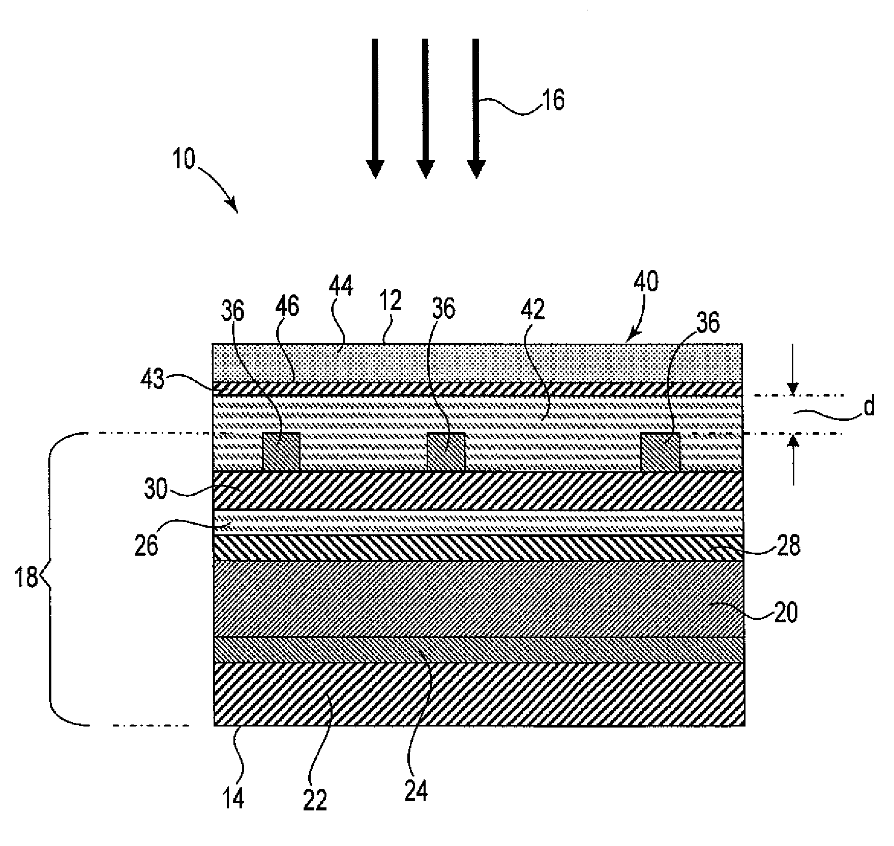
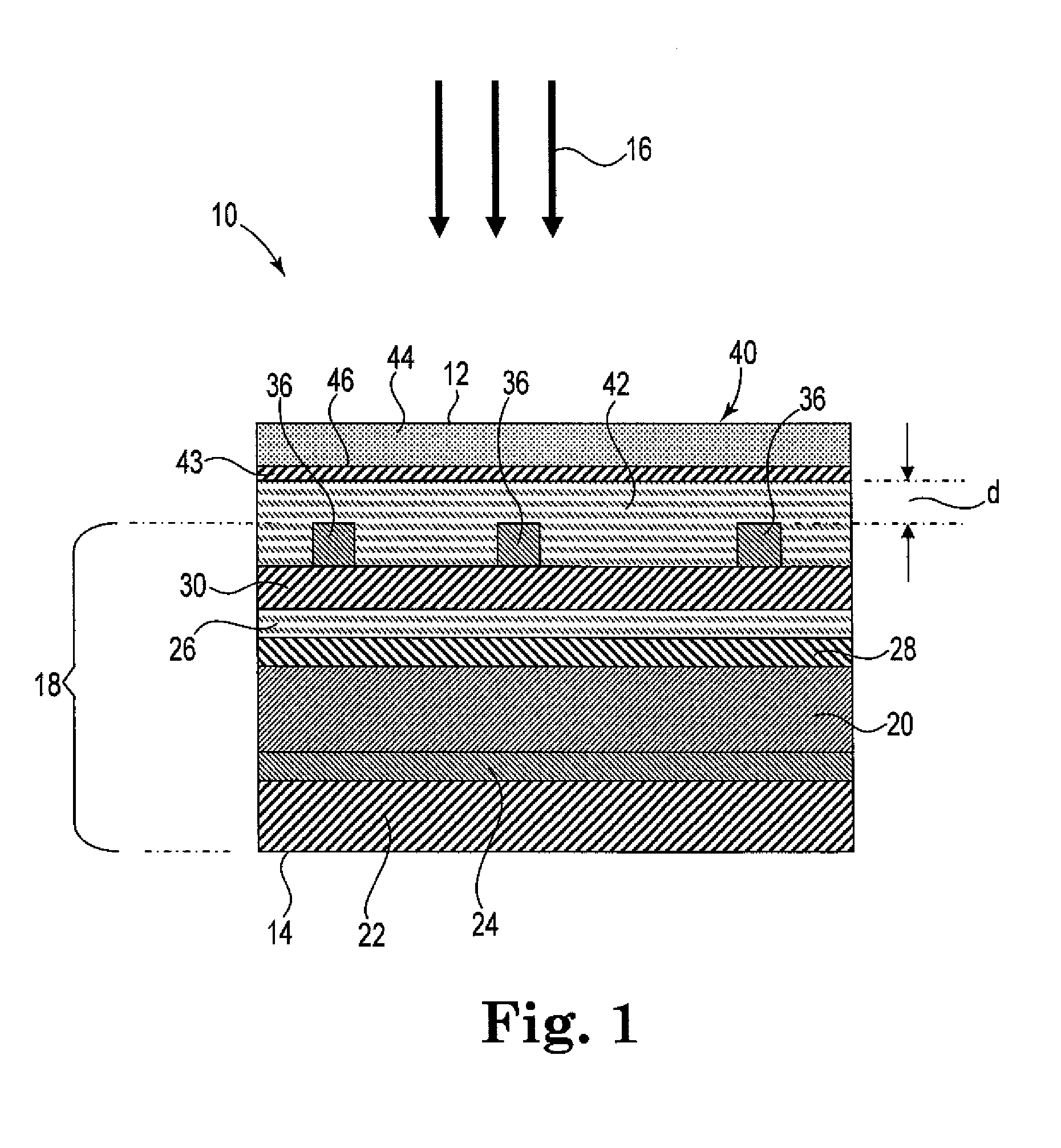
[0007]The present invention provides improved protection systems for CIGS-based microelectronic devices of the type incorporating electric conductor(s) such as an electronic collection grid. The protection systems of the invention incorporate elastomers with water vapor transmission rates that are atypically high in the context of CIGS-based devices. Quite surprisingly, even though the elastomeric material is highly permeable to water vapor, the integrated protection system still provides excellent protection against water damage.
[0008]The protection systems are incorporated into the devices such that the protection systems are positioned over and bury at least a portion of an underlying electronic collection grid. The protection systems not only protect the devices from the environment but also include features that accommodate and protect the devices from delamination stresses. Schematically, the protection systems can be viewed as incorporating an elastomeric region that functions as a three-dimensional shock absorber to help absorb and dissipate delamination stresses.
[0009]The systems accommodate stresses very well even when the elastomeric barrier is strongly bonded to the underlying electronic grid. This is significant, because the coupling between delamination stresses and such adhesion characteristics has been problematic in the past. As a consequence of this coupling, many conventional proposals for barrier films have been generally inadequate to give long term protection needed by chalcogenide-based solar cells. On one hand, some embodiments of conventional barrier films have tended to show poor adhesion to the top surface(s) of the device. In particular, the adhesion between barrier materials and underlying conductive collection grids may not have been as strong as desired. These adhesion issues can result in undue delamination or in a rupture of the continuous hermetic barrier film and / or provide open pathways allowing water intrusion to reach the chalcogenide compositions too easily. On the other hand, if the adhesion of the barrier film to the grid is strengthened using many conventional strategies, delamination stresses may tend to propagate through the grid and cause delamination issues elsewhere in the device. In short, both good adhesion and poor adhesion between conventional barrier films and the grid have led to delamination issues, resulting in device performance degradation and ultimately failure. The present invention is significant in that use of the elastomer layer would help to decouple delamination stresses from grid adhesion, thereby allowing strong grid adhesion to be practiced with a substantially reduced risk of delamination during cell life.

Problems solved by technology

This is significant, because the coupling between delamination stresses and such adhesion characteristics has been problematic in the past.
As a consequence of this coupling, many conventional proposals for barrier films have been generally inadequate to give long term protection needed by chalcogenide-based solar cells.
On one hand, some embodiments of conventional barrier films have tended to show poor adhesion to the top surface(s) of the device.
In particular, the adhesion between barrier materials and underlying conductive collection grids may not have been as strong as desired.
These adhesion issues can result in undue delamination or in a rupture of the continuous hermetic barrier film and / or provide open pathways allowing water intrusion to reach the chalcogenide compositions too easily.
On the other hand, if the adhesion of the barrier film to the grid is strengthened using many conventional strategies, delamination stresses may tend to propagate through the grid and cause delamination issues elsewhere in the device.
In short, both good adhesion and poor adhesion between conventional barrier films and the grid have led to delamination issues, resulting in device performance degradation and ultimately failure.

Method used


Image

  • Moisture resistant photovoltaic devices with elastomeric, polysiloxane protection layer
  • Moisture resistant photovoltaic devices with elastomeric, polysiloxane protection layer
  • Moisture resistant photovoltaic devices with elastomeric, polysiloxane protection layer

Examples


example 1

[0082]This example demonstrates that depositing a high WVTR silicone elastomer over CIGS-based cells protects cell efficiency and dramatically improves cell stability in damp environments.

Cell Preparation

[0083]All cells used in this example were the same and included a metal substrate, back electrical contact, CIGS absorber, CdS buffer, TCO, and top electrical conduction grid of silver. The individual CIGS based solar cells were electrically configured by welding a 1×10 mm Sn-plated copper busbar on the right and left side of the cell which represents the positive and negative terminals of the device, respectively. The busbar material extends past the top edge of the solar cell materials by approximately 3 inches to facilitate the electrical testing and monitoring of the device. These individual CIGS based solar cells were cleaned in a 50% (vol) water:50% isopropanol alcohol (vol) solution at 25° C. by simple hand agitation for 30 seconds. This was followed by a 30 minute heating to...

example 2

[0092]The coated cells prepared in Example 1 were subjected to damp heat testing at 85° C. and 85% relative humidity (RH). Retained efficiency as a function of this exposure was evaluated. For comparison, uncoated cells also were tested.

[0093]The purpose of damp heat testing is to evaluate the ability of a sample to withstand the effect of long-term humidity exposure and penetration. The testing is carried out according to IEC 60068-2-78 (2001-08) except that the room temperature cells were introduced into the testing chamber without preconditioning. Also, the following severities were applied:

Test temperature: 85° C. + / −2° C.

Relative Humidity: 85%+ / −5%

[0094]Test duration 1107 hr

[0095]The retained efficiency as a function of exposure is shown in the following table. All tabulated values are an average of three samples unless otherwise noted. A single data point was obtained for some of the cells due to the adhesive failing which attached the busbar to the cell.

% Retained Efficiency ...

example 3

Cell Preparation

[0097]All cells used in this example were the same except for the comparison as noted below. Each cell included a metal substrate, back electrical contact, CIGS absorber, CdS buffer, TCO, and top electrical conduction grid of silver. The individual CIGS based solar cells were electrically configured by welding a 1×10 mm Sn-plated copper busbar on the right and left side of the cell which represents the positive and negative terminals of the device. The busbar material extends past the top edge of the solar cell materials by approximately 3 inches to facilitate the electrical testing and monitoring of the device. These individual CIGS based solar cells were cleaned in a 50% (vol) water:50% isopropanol alcohol (vol) solution at 25° C. by simple hand agitation for 30 seconds. This was followed by a 30 minute heating to 50° C. in an oven.

Coating Formulations

[0098]The 3-1765 Conformal Coating product from Dow Corning Corporation, Midland, Mich. was used as received.

[0099]...


PUM


Abstract

Improved protection systems for CIGS-based microelectronic devices of the type incorporating electric conductor(s) such as an electronic collection grid. In one aspect, the present invention relates to a photovoltaic device having a light incident surface and a backside surface. The device includes a chalcogenide-containing photovoltaic layer comprising at least one of copper, indium and / or gallium. A transparent conductive layer is interposed between the photovoltaic layer and the light incident surface, wherein the transparent conductive layer is electrically coupled to the photovoltaic layer. An electronic collection grid is electrically coupled to the transparent conductive layer and overlying at least a portion of the transparent conductive layer. An elastomeric structure having a light incident surface, said structure overlying at least portions of the electronic collection grid and the transparent conductive layer in a manner such that the light incident surface of the elastomeric structure is spaced apart from a major portion of the conductor, and wherein the elastomeric structure comprises an elastomeric siloxane polymer having a WVTR of at least 0.1 g / m2-day. An optional protective barrier overlies the elastomeric structure. The protection systems of the invention incorporate elastomers with water vapor transmission rates that are atypically high in the context of CIGS-based devices.

Description

PRIORITY[0001]The present nonprovisional patent Application claims priority under 35 U.S.C. §119(e) from U.S. Provisional patent application having Ser. No. 61 / 292,646, filed on Jan. 6, 2010, by Popa et al. and titled MOISTURE RESISTANT PHOTOVOLTAIC DEVICES WITH ELASTOMERIC, POLYSILOXANE PROTECTION LAYER, wherein the entirety of said provisional patent application is incorporated herein by reference.FIELD OF THE INVENTION[0002]The present invention relates to photovoltaic devices of the type incorporating a conductive collection grid that facilitates ease of making external electrical connections, and more particularly to chalcogen-based photovoltaic devices in which the collection grid is contacted on at least one side by an elastomeric polysiloxane protection layer.BACKGROUND OF THE INVENTION[0003]Both n-type chalcogenide compositions and / or p-type chalcogenide compositions have been incorporated into components of photovoltaic devices. The p-type chalcogenide compositions have be...

Claims


Application Information

Patent Timeline
IPC IPC(8): H01L31/0216
CPCH01L31/048Y02E10/541H01L31/0749H01L31/0445H01L31/18
Inventor POPA, PAUL J.BOVEN, MICHELLE L.LYSENKO, ZENONMILLS, MICHAEL E.LOPEZ, LEONARDO C.
Owner DOW GLOBAL TECH LLC
Learn More