
Preparation of rare earth permanent magnet material

a permanent magnet material, rare earth technology, applied in the field of preparation of rare earth permanent magnet materials, can solve the problems of loss of remanence, inability to practically accept measurement, extreme productivity reduction, etc., and achieve high coercive force, high productivity, and high remanence

Active Publication Date: 2011-06-23
SHIN ETSU CHEM CO LTD
View PDF30 Cites 40 Cited by
  • Summary
  • Abstract
  • Description
  • Claims
  • Application Information

AI Technical Summary

Benefits of technology

[0014]The inventors have discovered that when a R1—Fe—B sintered magnet, typically a Nd—Fe—B sintered magnet is heated with a powder comprising one or more members selected from an oxide of R2, a fluoride of R3, and an oxyfluoride of R4 wherein R2, R3 and R4 each are one or more elements selected from among rare earth elements inclusive of Y and Sc being present in the magnet surface, R2, R3 or R4 contained in the powder is absorbed in the magnet form whereby the coercive force is increased while significantly suppressing a decline of remanence. Particularly when a fluoride of R3 or an oxyfluoride of R4 is used, R3 or R4 is efficiently absorbed in the magnet along with fluorine, resulting in a sintered magnet having a high remanence and a high coercive force. The present invention is predicated on this discovery.
[0032]The present invention ensures that a high-performance permanent magnet, especially a compact or thin permanent magnet, having a high remanence and a high coercive force is manufactured at a high productivity.

Problems solved by technology

Therefore, as long as the above approach is taken to increase coercive force, a loss of remanence is unavoidable.
To positively suppress the excessive diffusion into grains, lowering the sintering temperature may be effective, but this measure cannot be practically acceptable because it compromises densification by sintering.
An alternative method of sintering at lower temperatures while applying stresses by means of a hot press or the like enables densification, but poses the problem of extremely reduced productivity.
However, there is still left the problem of poor productivity associated with the deposition of metal coating by sputtering or the like.

Method used


Image

  • Preparation of rare earth permanent magnet material
  • Preparation of rare earth permanent magnet material
  • Preparation of rare earth permanent magnet material

Examples


example 2

[0076]By the same procedure as in Example 1, a magnet form of 20 mm×30 mm×3 mm was prepared.

[0077]Dysprosium oxyfluoride having an average particle size of 10 μm was mixed with ethanol at a weight fraction of 50%, in which the magnet form was immersed for one minute with ultrasonic waves being applied. The magnet form was pulled up and immediately dried with hot air. At this point, the filling factor of dysprosium oxyfluoride in the magnet surface-surrounding space was 45%. The magnet form was subjected to absorption treatment in an argon atmosphere at 900° C. for one hour, then to aging treatment at 500° C. for one hour, and quenched, obtaining a magnet form designated M2.

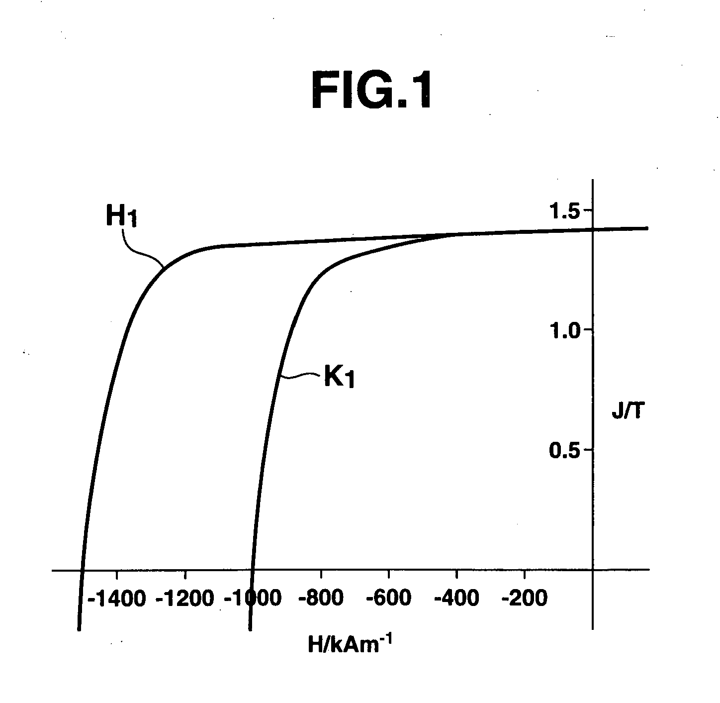
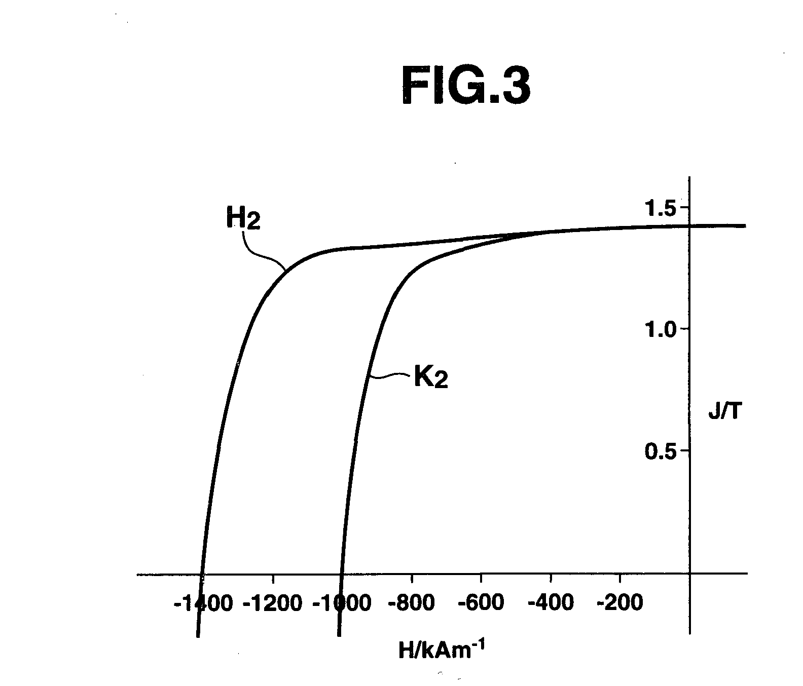
[0078]The magnetic properties of magnet form M2 are also shown in Table 1. The inventive magnet was found to offer an increase in coercive force of 470 kAm−1 relative to the coercive force of the magnet P1 which had not been subjected to dysprosium absorption treatment. A drop of remanence was 3 mT.

example 3

[0079]By the same procedure as in Example 1, a magnet form of 10 mm×20 mm×1.5 mm was prepared.

[0080]Terbium fluoride having an average particle size of 5 μm was mixed with ethanol at a weight fraction of 50%, in which the magnet form was immersed for one minute with ultrasonic waves being applied. The magnet form was pulled up and immediately dried with hot air. At this point, the filling factor of terbium fluoride in the magnet surface-surrounding space was 45%. The magnet form was subjected to absorption treatment in an argon atmosphere at 900° C. for one hour, then to aging treatment at 500° C. for one hour, and quenched, obtaining a magnet form designated M3.

[0081]The magnetic properties of magnet form M3 are also shown in Table 1. The inventive magnet was found to offer an increase in coercive force of 800 kAm-1 relative to the coercive force of the magnet P1 which had not been subjected to terbium absorption treatment. A drop of remanence was 5 mT.


PUM

PropertyMeasurementUnit
particle sizeaaaaaaaaaa
temperatureaaaaaaaaaa
volume fractionaaaaaaaaaa

Abstract

A method for preparing a rare earth permanent magnet material comprises the steps of: disposing a powder comprising one or more members selected from an oxide of R2, a fluoride of R3, and an oxyfluoride of R4 wherein R2, R3 and R4 each are one or more elements selected from among rare earth elements inclusive of Y and Sc on a sintered magnet form of a R1—Fe—B composition wherein R1 is one or more elements selected from among rare earth elements inclusive of Y and Sc, and then heat treating the magnet form and the powder at a temperature equal to or below the sintering temperature of the magnet in vacuum or in an inert gas. The result high performance, compact or thin permanent magnet has a high remanence and coercivity at a high productivity.

Description

INCORPORATED-BY-REFERENCE TO RELATED APPLICATIONS[0001]This application is a divisional application of U.S. Ser. No. 10 / 572,753, filed Mar. 21, 2006, which is a National Stage Entry of PCT / JP05 / 05134 and claims the benefit of priority from Japanese Patent Application No. 2004-304543, filed on Oct. 19, 2004 and Japanese patent Application No. 2004-377379, filed on Dec. 27, 2004, the entire contents of which being incorporated herein by reference.TECHNICAL FIELD[0002]This invention relates to a method for preparing a R—Fe—B system permanent magnet in which the coercive force of a sintered magnet form is enhanced while controlling a decline of its remanence; and more particularly, to a method for preparing a high performance, compact or thin rare earth permanent magnet material.BACKGROUND ART[0003]Nd—Fe—B system permanent magnets have a growing range of application due to their excellent magnetic properties. While electronic equipment having magnets built therein including computer-rel...

Claims


Application Information

Patent Timeline
Patent Type & Authority Applications(United States)
IPC IPC(8): B22F3/12B22F3/24
CPCB22F9/023H01F41/0293B22F2998/10B22F2999/00H01F1/0577B22F2009/044H01J37/32669B22F9/04B22F3/02B22F3/10B22F2201/11B22F2201/02H01F7/02
Inventor NAKAMURA, HAJIMEHIROTA, KOICHIMINOWA, TAKEHISA
Owner SHIN ETSU CHEM CO LTD
Learn More