
Heat-transfer arrangement for enclosed circuit boards

Inactive Publication Date: 2011-06-23
ALCATEL LUCENT SAS
View PDF12 Cites 20 Cited by
  • Summary
  • Abstract
  • Description
  • Claims
  • Application Information

AI Technical Summary

Benefits of technology

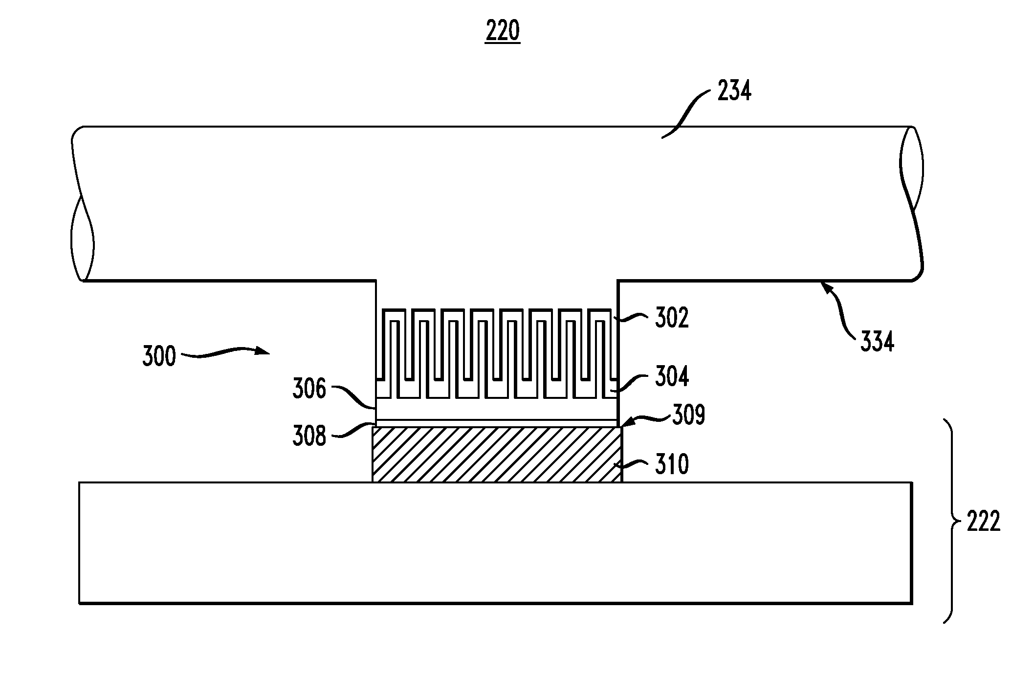
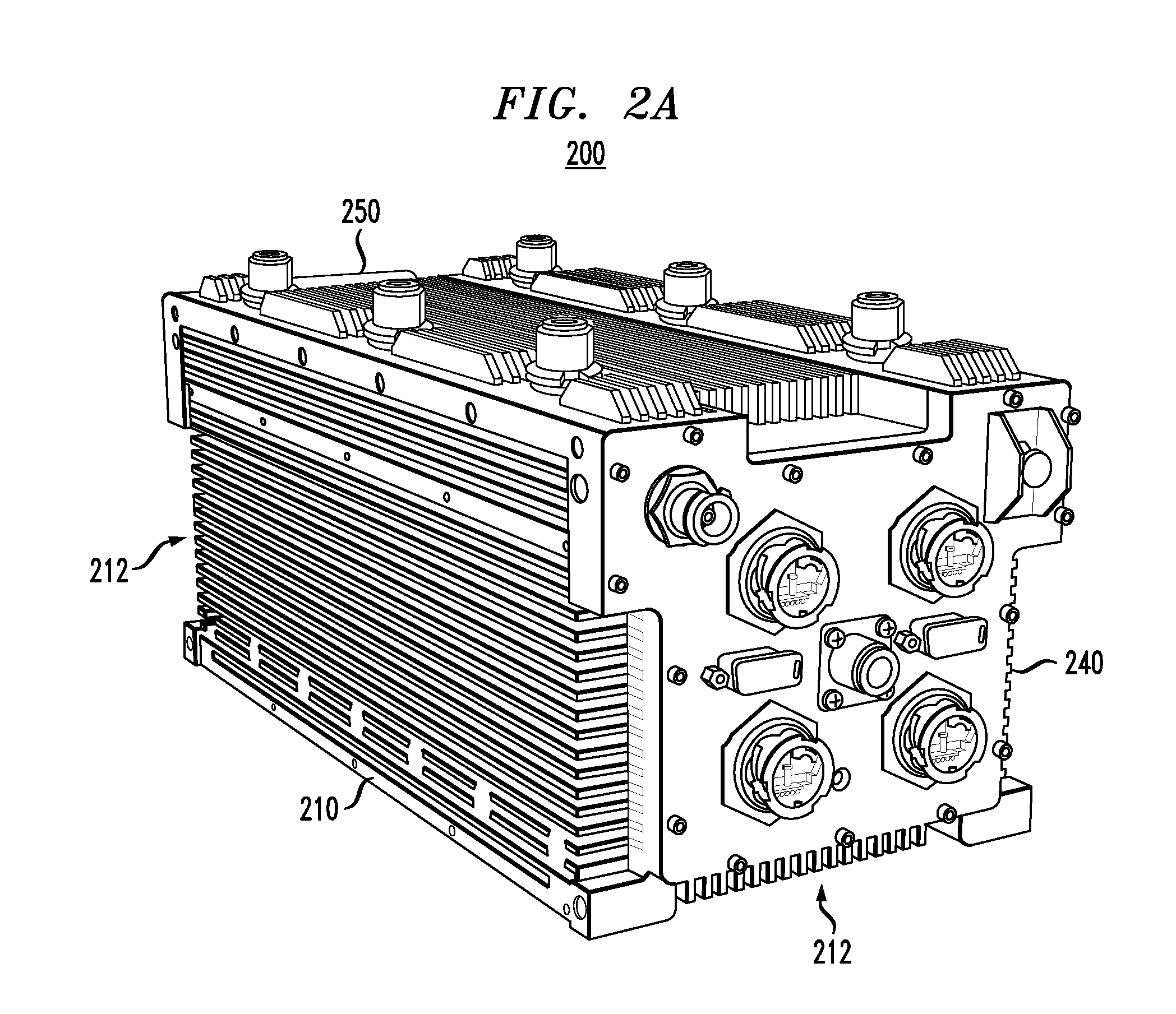
[0006]Disclosed herein are various embodiments of an electronics module designed to efficiently remove heat from enclosed circuit boards via one or more configurable heat conduits. Each heat conduit is custom-configured to provide good thermal contact between the corresponding heat-generating electronic device of an enclosed circuit board and the clamshell housing that encloses the circuit board. Good thermal contact between the clamshell housing and the outer case of the electronic module facilitates efficient heat transfer to the finned exterior surface of the outer case, where the heat is dissipated into the ambient environment via thermal conduction, natural convection, forced convection, and / or thermal radiation. Depending on the topology of the circuit board and the individual characteristics of the electronic device to be cooled, the corresponding configurable heat conduit might be based on a nested heat-sink coupler, a fitted movable plug, or a flexible ribbon-shaped heat pipe.

Problems solved by technology

A typical circuit board has a plurality of densely packed electronic devices mounted thereon, which results in a rather complicated overall surface topology of varying heights, shapes, and profiles.
However, the complicated and varying surface topology of the circuit boards and their side-by-side mounting arrangement make it relatively difficult to remove the heat from the electronics module in a desired efficient manner.

Method used


Image

  • Heat-transfer arrangement for enclosed circuit boards
  • Heat-transfer arrangement for enclosed circuit boards
  • Heat-transfer arrangement for enclosed circuit boards

Examples


Embodiment Construction

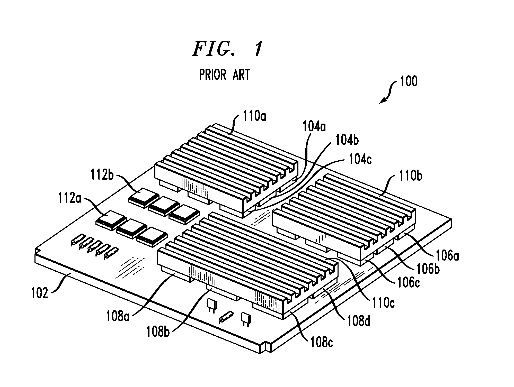
[0015]FIG. 1 shows a three-dimensional perspective view of a circuit board 100 having attached thereto three prior-art heat sinks 110a-c. More specifically, circuit board 100 comprises a plurality of electronic devices, e.g., integrated circuits, mounted on an epoxy-composite base board (e.g., printed wiring board, PWB) 102. Each heat sink 110 is attached to a corresponding group of devices, with all devices within the group preferably having similar shapes and dimensions. For example, heat sink 110a is attached to a group having nine devices 104; heat sink 110b is attached to a group having nine devices 106; and heat sink 110c is attached to a group having six devices 108. In addition, a heat sink similar to heat sink 110 can be attached to each individual heat-generating device, e.g., integrated circuit 112.

[0016]Each heat sink 110 is fabricated of a material having good thermal conductivity, e.g., aluminum or copper, and has the shape of a plate with fins extending from one side ...


PUM


Abstract

An electronics module designed to efficiently remove heat from enclosed circuit boards via one or more configurable heat conduits. Each heat conduit is custom-configured to provide good thermal contact between the corresponding heat-generating electronic device of an enclosed circuit board and the clamshell housing that encloses the circuit board. Good thermal contact between the clamshell housing and the outer case of the electronic module facilitates efficient heat transfer to the finned exterior surface of the outer case, where the heat is dissipated into the ambient environment via thermal conduction, natural convection, forced convection, and / or thermal radiation. Depending on the topology of the circuit board and the individual characteristics of the electronic device to be cooled, the corresponding configurable heat conduit might be based on a nested heat-sink coupler, a fitted movable plug, or a flexible ribbon-shaped heat pipe.

Description

BACKGROUND[0001]1. Field of the Invention[0002]The present invention relates to cooling heat-generating electronic devices and, more specifically but not exclusively, to heat removal from enclosed circuit boards.[0003]2. Description of the Related Art[0004]This section introduces aspects that may help facilitate a better understanding of the invention(s). Accordingly, the statements of this section are to be read in this light and are not to be understood as admissions about what is in the prior art or what is not in the prior art.[0005]A typical circuit board has a plurality of densely packed electronic devices mounted thereon, which results in a rather complicated overall surface topology of varying heights, shapes, and profiles. Moreover, circuit boards of different types normally have very different surface topologies. In a typical electronics module, multiple circuit boards of different types are mounted side by side inside an electronics case. To maintain electronic devices wi...

Claims


Application Information

Patent Timeline
IPC IPC(8): H05K7/20
CPCH05K7/20454H05K7/20672H05K7/20545
Inventor SALAMON, TODD R.KOLODNER, PAUL R.
Owner ALCATEL LUCENT SAS
Learn More