
Full spectrum LED illuminator

a full spectrum led illuminator and led light technology, applied in the field of illumination systems, can solve the problems of limited to optical imaging applications, leds and/or laser diodes, and the challenge of full visible spectrum illumination with solid state light sources

Active Publication Date: 2015-03-17
STRYKER EUROPEAN OPERATIONS LIMITED
View PDF25 Cites 39 Cited by
  • Summary
  • Abstract
  • Description
  • Claims
  • Application Information

AI Technical Summary

Benefits of technology

The present invention is an illuminator that uses solid state light sources to produce a bright, color balanced, broad-spectrum, visible light output. The LED light sources are mounted on a heat sink in good thermal contact with a single heat spreader plate, which can be a metal plate with high thermal conductivity. The LEDs and the spreader plate are connected through a thermally conductive compound or soldering. The LEDs are positioned at different optical paths, and an aspheric lens is used to collect the light from each LED. The aspheric lens projects a nearly collimated light beam onto a mirror or dichroic filter, which reflects the light at a right angle and transmits the light of all shorter wavelengths. The power and position of each lens and the field lens are adjusted to manage the etendue constraints and maximize the coupling of the high NA lens into an optical light guide. The technical effects of the invention are improved cost / complexity and cooling efficiency, and enhanced collection efficiency of the LED light sources.

Problems solved by technology

Due to the output brightness or output spectrum limitations of these solid state light sources, the use of LEDs and / or laser diodes has, until recently, been limited to optical imaging applications where low light levels are sufficient or where narrow spectrum illumination is required / desired.
Achieving sufficiently bright, full visible spectrum illumination with solid state light sources has remained challenging for a number of reasons.
Moreover, etendue considerations rapidly constrain the practical implementation of such combined source illumination systems.
c) Should the etendue considerations with a multiple different colored LED arrangement be overcome by a suitable arrangement of sources and dichroics with optical path lengths that are carefully equalized, then other implementation issues arise with respect to effective cooling and cost.

Method used


Image

  • Full spectrum LED illuminator
  • Full spectrum LED illuminator
  • Full spectrum LED illuminator

Examples


Embodiment Construction

[0025]Throughout all the figures, same or corresponding elements may generally be indicated by same reference numerals. These depicted embodiments are to be understood as illustrative of the invention and not as limiting in any way. It should also be understood that the figures are not necessarily to scale and that the embodiments are sometimes illustrated by graphic symbols, phantom lines, diagrammatic representations and fragmentary views. In certain instances, details which are not necessary for an understanding of the present invention or which render other details difficult to perceive may have been omitted,

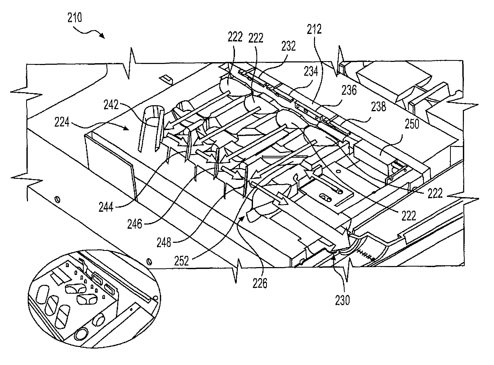
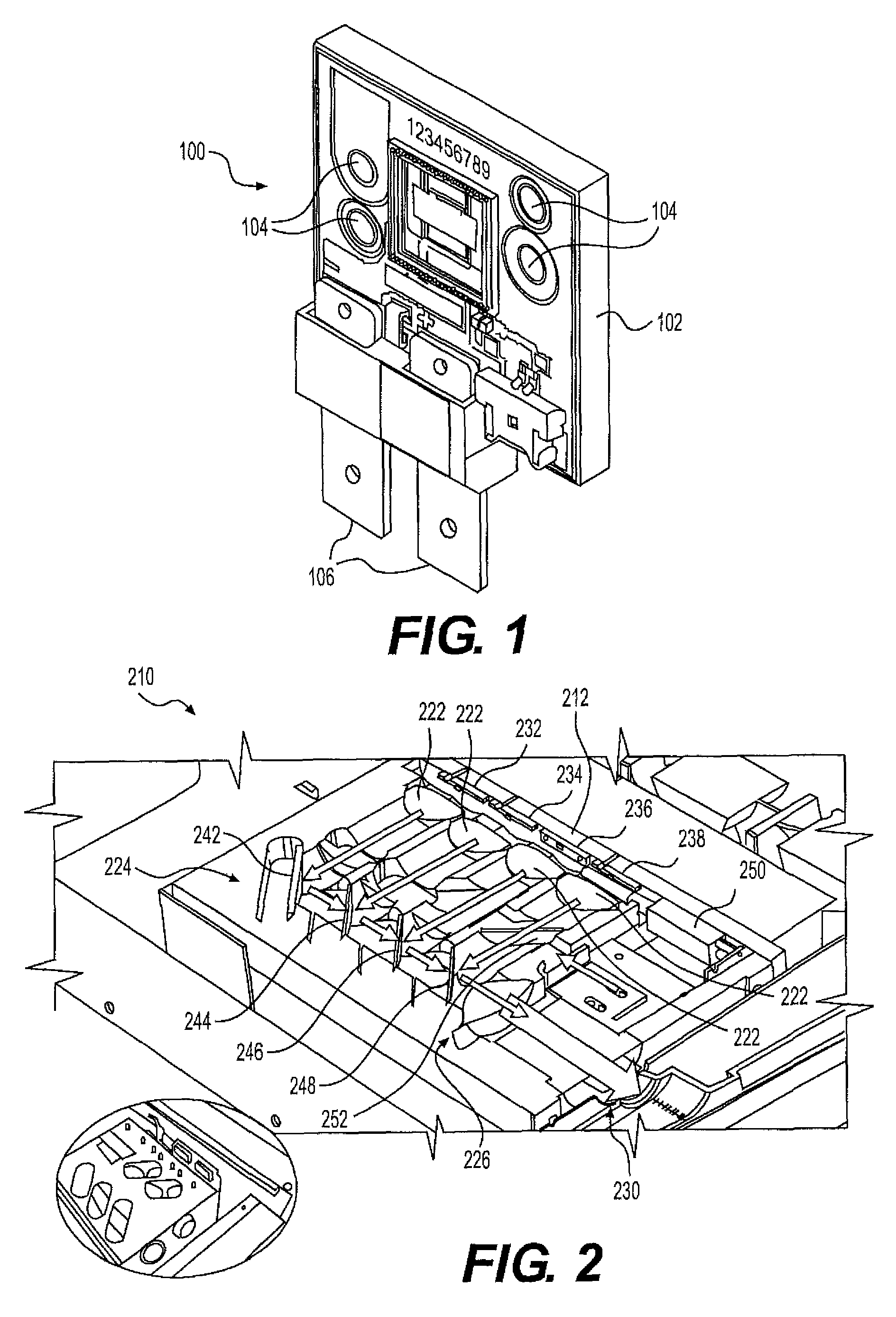
[0026]Turning now to the drawing, and in particular to FIG. 1, there is shown an LED package 100 including a substrate 102 with high thermal conductivity having mounting holes 104 for attachment to a heat spreader 212 shown in FIG, 2. The LED package also includes electrical terminals 106 for supplying electric power to the LEDs.

[0027]FIG. 2 shows in a cut-away view an illum...


PUM


Abstract

An apparatus for providing a light output to an optical guide for illumination of an imaged object including a plurality of solid state light-emitting sources each of which are independently powered and independently controlled, each light-emitting source emitting light at a wavelength which is different from the wavelength emitted by the other light-emitting sources. The apparatus also includes a heat sink configured to thermally couple the plurality of solid state light-emitting sources and provide conduction of heat generated by the plurality of solid state light-emitting sources. The apparatus further includes an optical elements to collect, collimate, and combine the emissions from the plurality of solid state light-emitting sources into a combined beam of light to be optically coupled to the light guide.

Description

BACKGROUND OF THE INVENTION[0001]The present invention relates to an illumination system, in particular for endoscopy, and more particularly a full spectrum illumination system using light-emitting diodes (LED) and / or semiconductor lasers.[0002]Illumination systems for endoscopy, microscopy and similar optical imaging applications have for many years utilized arc lamp or halogen technology as the light source of choice. More recently, various forms of solid state light sources such as light emitting diodes or diode lasers have been introduced for use in some of these imaging applications. Due to the output brightness or output spectrum limitations of these solid state light sources, the use of LEDs and / or laser diodes has, until recently, been limited to optical imaging applications where low light levels are sufficient or where narrow spectrum illumination is required / desired.[0003]Achieving sufficiently bright, full visible spectrum illumination with solid state light sources has ...

Claims


Application Information

Patent Timeline
Patent Type & Authority Patents(United States)
IPC IPC(8): F21V13/02F21V9/00A61B1/06
CPCA61B1/063A61B1/0638A61B1/0684F21Y2115/30F21Y2115/10F21Y2113/13F21K9/60A61B1/046F21V9/08F21K9/61F21V29/74F21V5/045F21V29/56G02B27/30A61B1/00006F21V29/70F21V29/89A61B2090/306A61B2090/309F21Y2103/10A61B1/128A61B5/0071F21V15/01F21V23/02G02B6/0001G02B23/2469
Inventor MOORE, ALLEN
Owner STRYKER EUROPEAN OPERATIONS LIMITED
Learn More